Automotive SPICE®
Process Reference Model
Process Assessment Model
Version 4.0
Title: |
Automotive SPICE Process Assessment / Reference Model |
Author(s): |
VDA Working Group 13 |
Version: |
4.0 |
Date: |
2023-11-29 |
Status: |
Released |
Copyright notice
This document is a revision of the Automotive SPICE process assessment model and process reference model 3.1, which has been developed by the Working Group 13 of the Quality Management Center (QMC) in the German Association of the Automotive Industry.
This document reproduces relevant material from:
ISO/IEC 33020:2019
Information technology – Process assessment – Process measurement framework for assessment of process capability
ISO/IEC 33020:2019 provides the following copyright release statement:
‘Users of this International Standard may reproduce subclauses 5.2, 5.3, 5.4 and 5.6 as part of any process assessment model or maturity model so that it can be used for its intended purpose.’
ISO/IEC 15504-5:2006
Information Technology – Process assessment – Part 5: An exemplar Process Assessment Model
ISO/IEC 15504-5:2006 provides the following copyright release statement:
‘Users of this part of ISO/IEC 15504 may freely reproduce the detailed descriptions contained in the exemplar assessment model as part of any tool or other material to support the performance of process assessments, so that it can be used for its intended purpose.’
Relevant material from one of the mentioned standards is incorporated under the copyright release notice.
Acknowledgement
The VDA, the VDA QMC and the Project Group 13 explicitly acknowledge the high-quality work carried out by the members of the intacs® working groups. We would like to thank all involved people who have contributed to the development and publication of Automotive SPICE®.
Derivative works
You may not alter, transform, or build upon this work without the prior consent of the VDA Quality Management Center. Such consent may be given provided ISO copyright is not infringed.
The detailed descriptions contained in this document may be incorporated as part of any tool or other material to support the performance of process assessments, so that this process assessment model can be used for its intended purpose, provided that any such material is not offered for sale.
All distribution of derivative works shall be made at no cost to the recipient.
Document distribution
The Automotive SPICE® process assessment model may only be obtained by download from the www.vda-qmc.de web site. It is not permitted for the recipient to further distribute the document.
Change requests
Any problems or change requests should be reported through the defined mechanism at the www.vda-qmc.de web site.
Trademark notice
Automotive SPICE® is a registered trademark of the Verband der Automobilindustrie e.V. (VDA) For further information about Automotive SPICE® visit www.vda-qmc.de.
Document history
Version |
Date |
By |
Notes |
|---|---|---|---|
2.0 |
2005-05-04 |
AutoSIG / SUG |
DRAFT RELEASE, pending final editorial review |
2.1 |
2005-06-24 |
AutoSIG / SUG |
Editorial review comments implemented Updated to reflect changes in FDIS 15504-5 |
2.2 |
2005-08-21 |
AutoSIG / SUG |
Final checks implemented: FORMAL RELEASE |
2.3 |
2007-05-05 |
AutoSIG / SUG |
Revision following CCB: FORMAL RELEASE |
2.4 |
2008-08-01 |
AutoSIG / SUG |
Revision following CCB: FORMAL RELEASE |
2.5 |
2010-05-10 |
AutoSIG / SUG |
Revision following CCB: FORMAL RELEASE |
3.0 |
2015-07-16 |
VDA QMC WG13 |
Changes: See release notes |
3.1 |
2017-11-01 |
VDA QMC WG13 |
Changes: See www.automotivespice.com |
4.0 |
2023-10-20 |
VDA QMC WG13 |
Complete revision of PAM |
Table of contents
3. Process capability determination 15
3.1. Process reference model 16
3.1.1. Primary life cycle processes category 17
3.1.2. Supporting life cycle processes category 20
3.1.3. Organizational life cycle processes category 20
3.2.1. Process capability levels and process attributes 21
3.2.2. Process attribute rating 23
3.2.3. Rating and aggregation method 24
3.2.4. Process capability level model 26
3.3. Process assessment model 27
3.3.1. Assessment indicators 28
3.3.2. Understanding information Items and work products 29
3.3.3. Understanding the level of abstraction of a PAM 31
3.3.4. Why a PRM and PAM are not a lifecycle model or development process blueprint 31
4. Process reference model and performance indicators (Level 1) 33
4.1. Acquisition process group (ACQ) 34
4.1.1. ACQ.4 Supplier Monitoring 34
4.2. Supply process group (SPL) 37
4.2.1. SPL.2 Product Release 37
4.3. System engineering process group (SYS) 40
4.3.1. SYS.1 Requirements Elicitation 40
4.3.2. SYS.2 System Requirements Analysis 43
4.3.3. SYS.3 System Architectural Design 46
4.3.4. SYS.4 System Integration and Integration Verification 49
4.3.5. SYS.5 System Verification 52
4.4. Software engineering process group (SWE) 55
4.4.1. SWE.1 Software Requirements Analysis 55
4.4.2. SWE.2 Software Architectural Design 58
4.4.3. SWE.3 Software Detailed Design and Unit Construction 61
4.4.4. SWE.4 Software Unit Verification 64
4.4.5. SWE.5 Software Component Verification and Integration Verification 67
4.4.6. SWE.6 Software Verification 71
4.5. Validation process group (VAL) 74
4.6. Machine Learning Engineering process group (MLE) 77
4.6.1. MLE.1 Machine Learning Requirements Analysis 77
4.6.2. MLE.2 Machine Learning Architecture 80
4.6.3. MLE.3 Machine Learning Training 83
4.6.4. MLE.4 Machine Learning Model Testing 86
4.7. Hardware Engineering process group (HWE) 90
4.7.1. HWE.1 Hardware Requirements Analysis 90
4.7.2. HWE.2 Hardware Design 94
4.7.3. HWE.3 Verification against Hardware Design 97
4.7.4. HWE.4 Verification against Hardware Requirements 100
4.8. Supporting process group (SUP) 103
4.8.1. SUP.1 Quality Assurance 103
4.8.2. SUP.8 Configuration Management 106
4.8.3. SUP.9 Problem Resolution Management 110
4.8.4. SUP.10 Change Request Management 113
4.8.5. SUP.11 Machine Learning Data Management 116
4.9. Management process group (MAN) 119
4.9.1. MAN.3 Project Management 119
4.9.2. MAN.5 Risk Management 123
4.10. Process improvement process group (PIM) 129
4.10.1. PIM.3 Process Improvement 129
4.11. Reuse process group (REU) 132
4.11.1. REU.2 Management of Products for Reuse 132
5. Process capability levels and process attributes 135
5.1. Process capability level 0: Incomplete process 135
5.2. Process capability Level 1: Performed process 135
5.2.1. PA 1.1 Process performance process attribute 136
5.3. Process capability Level 2: Managed process 136
5.3.1. PA 2.1 Process performance management process attribute 137
5.3.2. PA 2.2 Work product management process attribute 141
5.4. Process capability Level 3: Established process 143
5.4.1. PA 3.1 Process definition process attribute 144
5.4.2. PA 3.2 Process deployment process attribute 147
5.5. Process capability Level 4: Predictable process 150
5.5.1. PA 4.1 Quantitative analysis process attribute 150
5.5.2. PA 4.2 Quantitative control process attribute 153
5.6. Process capability Level 5: Innovating process 155
5.6.1. PA 5.1 Process innovation process attribute 155
5.6.2. PA 5.2 Process innovation implementation process attribute 157
Annex A Conformity statements 160
Annex A.2 Conformance to the requirements for process reference models 160
Annex A.3 Conformance to the requirements for process assessment models 160
Annex A.4 Conformance to the requirements for measurement frameworks 162
Annex B Information Item Characteristics 163
Annex C Key concepts and guidance 185
Annex C.1 The “Plug-in” concept 185
Annex C.2 “Element”, “Component”, and “Unit” 186
Annex C.3 Integration of Machine Learning Engineering Processes 187
Annex C.4 Example of an ML Architecture 189
Annex C.5 Traceability and consistency 190
Annex C.6 “Agree” and “Summarize and Communicate” 192
Annex C.7 Key Changes in Automotive SPICE 4.0 193
Terminology – “Measure” vs. “Metric” 193
Terminology – “Affected Party” (Level 1) vs. “Involved Party” (Level 2) 193
List of Figures
Figure 1 — Process assessment model relationship 15
Figure 2 — Automotive SPICE process reference model – Overview 16
Figure 3 — Automotive SPICE process reference model – Overview4 16
Figure 4 — Relationship between assessment indicators and process capability 29
Figure 5 — Possible levels of abstraction for the term “process” 31
Figure 6 — Performing a process assessment for determining process capability 32
List of Tables
Table 2 — Abbreviation List 14
Table 3 — Primary life cycle processes – ACQ process group 18
Table 4 — Primary life cycle processes – SPL process group 18
Table 5 — Primary life cycle processes – SYS process group 18
Table 6 — Primary life cycle processes – VAL process group 19
Table 7 — Primary life cycle processes – SWE process group 19
Table 8 — Primary life cycle processes – MLE process group 19
Table 9 — Primary life cycle processes – HWE process group 19
Table 10 — Supporting life cycle processes - SUP process group 20
Table 11 — Organizational life cycle processes - MAN process group 20
Table 12 — Organizational life cycle processes - PIM process group 20
Table 13 — Organizational life cycle processes - REU process group 20
Table 14 — Process capability levels 21
Table 15 — Process attributes 22
Table 17 — Rating scale percentage values 23
Table 18 — Refinement of rating scale 24
Table 19 — Refined rating scale percentage values 24
Table 20 — Capability levels and corresponding process attribute ratings 27
Table 21 — Template for the process description 33
Table B. 1 — Structure of information item characteristics (IIC) table 163
1. Introduction
1.1. Scope
Process assessment is a disciplined evaluation of an organizational unit’s processes against a process assessment model.
The Automotive SPICE process assessment model (PAM) is intended for use when performing conformant assessments of the process capability on the development of embedded automotive systems. It was developed in accordance with the requirements of ISO/IEC 33004:2015.
Automotive SPICE has its own process reference model (PRM), which was developed based on the Automotive SPICE process reference model 4.5. It was further developed and tailored considering the specific needs of the automotive industry. If processes beyond the scope of Automotive SPICE are needed, appropriate processes from other process reference models such as ISO/IEC 12207 or ISO/IEC/IEEE 15288 may be added based on the business needs of the organization.
The PRM is incorporated in this document and is used in conjunction with the Automotive SPICE process assessment model when performing an assessment.
This Automotive SPICE process assessment model contains a set of indicators to be considered when interpreting the intent of the Automotive SPICE process reference model. These indicators may also be used when implementing a process improvement program.
1.2. Terminology
Automotive SPICE follows the following precedence for use of terminology:
ISO/IEC 33001 for assessment related terminology
ISO/IEC/IEEE 24765, ISO/SAE 21434 and ISO/IEC/IEEE 29119 terminology (as contained in Annex C)
Terms introduced by Automotive SPICE (as contained in Annex C)
PMBOK® Guide – Fourth Edition
PAS 1883:2020
Term |
Origin |
Description |
|---|---|---|
Activity |
Automotive SPICE V4.0 |
Execution of a task by a stakeholder or an involved party. |
Application parameter |
Automotive SPICE V4.0 |
An application parameter is a software variable containing data that can be changed at the system or software levels; they influence the system’s or software behavior and properties. The notion of application parameter is expressed in two ways:
Application parameters are not requirements. They are a technical implementation solution for configurability-oriented requirements. |
Approval |
Automotive SPICE V4.0 |
Written statement that a deliverable is fit for its intended use, and compliant with defined criteria. |
Baseline |
Automotive SPICE V4.0 |
A defined and coherent set of read-only information, serving as an input information the for affected parties. |
Deliverable |
PMBOK® Guide – Fourth Edition |
Any unique and verifiable product, result, or capability to perform a service that must be produced to complete a process, phase, or project. Often used more narrowly in reference to an external deliverable, which is a deliverable that is subject to approval by the project sponsor or customer. |
Functional requirement |
ISO/IEC/IEEE 24765 |
A statement that identifies what a product or process must accomplish to produce required behavior and/or results. |
Hardware |
intacs® working group HW PAM |
Assembled and interconnected electrical or electronic hardware components or parts which perform analog or digital functions or operations. |
Hardware component |
intacs® working group HW PAM |
Logical (e.g., functional block) or physical group of hardware parts realizing a functionality, which
|
Hardware element |
intacs® working group HW PAM |
Generic term; can represent a hardware component, a hardware part, a hardware interface, or the hardware. |
Hardware part |
Automotive SPICE V4.0 |
Fundamental HW element the purpose and functionality of which cannot be further subdivided or separated.
|
Hyperparameter |
Automotive SPICE V4.0 |
In machine learning, a hyperparameter is a parameter whose value is used to control the training of the ML model. Its value must be set between training iterations. Examples: learning rate, loss function, model depth, regularization constants. |
Information need |
Automotive SPICE V4.0 |
The need for characterizing process or product related effectiveness and efficiency (used by MAN.6 and PA 4.1). |
Machine Learning (ML) |
Automotive SPICE V4.0 |
In Automotive SPICE Machine Learning (ML) describes the ability of software to learn from specific training data and to apply this knowledge to other similar tasks. |
Measure |
Automotive SPICE V4.0 |
An activity to achieve a certain intent. |
Measurement |
Oxford Dictionary |
“The activity to find the size, quantity or degree of something”. |
Metric |
Automotive SPICE V4.0 |
A quantitative or qualitative measurable indicator that matches defined information needs. |
Operational Design Domain |
PAS 1883:2020 |
Operational Design Domain (ODD) is operating conditions under which a given overall system or feature thereof is specifically designed to function. This includes, but is not limited to, environmental, geographical, and time-of-day restrictions, and/or the requisite presence or absence of certain traffic or roadway characteristics. |
Project |
ISO/IEC/IEEE 24765 |
Endeavor with defined start and finish dates undertaken to create a product or service in accordance with specified resources and requirements. |
Release |
Automotive SPICE V4.0 |
A physical product delivered to a customer, including a defined set of functionalities and properties. |
Regression verification |
Automotive SPICE V4.0 |
Selective re-verification of elements to verify that modifications have not caused unintended effects. |
Risk |
ISO/IEC/IEEE 24765 |
The combination of the probability of occurrence and the consequences of a given future undesirable event. |
Software component |
Automotive SPICE V4.0 |
Software component in design and implementation-oriented processes: The software architecture decomposes the software into software components across appropriate hierarchical levels down to the lowest-level software components in a conceptual model. Software component in verification-oriented processes: The implementation of a SW component under verification is represented e.g., as source code, object files, library file, executable, or executable model. |
Software element |
Automotive SPICE V4.0 |
Refers to software component or software unit |
Software unit |
Automotive SPICE V4.0 |
Software unit in design and implementation-oriented processes: As a result of the decomposition of a software component, the software is decomposed into software units which are a representation of a software element, which is decided not to be further subdivided and that is a part of a software component at the lowest level, in a conceptual model. Software unit in verification-oriented processes: An implemented SW unit under verification is represented e.g., as source code files, or an object file. |
Stakeholder requirements |
Automotive SPICE V4.0 |
Any type of requirement for the stakeholders in the given context, e.g., customer requirement, supplier internal requirements (product-specific, platform etc.), legal requirements, regulatory requirements, statutory requirements, industry sector requirements, international standards, codes of practice etc. … |
System Element |
Automotive SPICE V4.0 |
System elements can be:
|
Task |
Automotive SPICE V4.0 |
A definition, but not the execution, of a coherent and set of atomic actions. |
Validation measure |
Automotive SPICE V4.0 |
Validation measure can be:
|
Verification |
Automotive SPICE V4.0 |
Verification is confirmation through the provision of objective evidence that an element fulfils the specified requirements. |
Verification measure |
Automotive SPICE V4.0 |
Verification measure can be:
Note, that in particular domains certain verification measures may not be applicable, e.g., software units generally cannot be verified by means of calculations or analyses. |
1.3. Abbreviations
BP |
Base Practice |
CAN |
Controller Area Network |
CASE |
Computer-Aided Software Engineering, |
CCB |
Change Control Board |
CPU |
Central Processing Unit |
ECU |
Electronic Control Unit |
EEPROM |
Electrically Erasable Programmable Read Only Memory |
EOL |
End-of-Line |
FMEA |
Failure Mode and Effect Analysis |
FTA |
Fault Tree Analysis |
GP |
Generic Practice |
GR |
Generic Resource |
IEC |
International Electrotechnical Commission |
IEEE |
Institute of Electrical and Electronics Engineers |
I/O |
Input / Output |
ISO |
International Organization for Standardization |
LIN |
Local Interconnect Network |
MISRA |
Motor Industry Software Reliability Association |
MOST |
Media Oriented Systems Transport |
ODD |
Operational Design Domain |
PA |
Process Attribute |
PAM |
Process Assessment Model |
PRM |
Process Reference Model |
PWM |
Pulse Width Modulation |
RAM |
Random Access Memory |
ROM |
Read Only Memory |
SPICE |
Systems Process Improvement and Capability dEtermination |
SUG |
Spice User Group |
USB |
Universal Serial Bus |
WP |
Work Product |
WPC |
Work Product Characteristic |
2. Statement of compliance
The Automotive SPICE process reference model and process assessment model are conformant with the ISO/IEC 33004:2015 and can be used as the basis for conducting an assessment of process capability.
An ISO/IEC 33003:2015 compliant Measurement Framework is defined in section 5.
A statement of compliance of the process assessment model and process reference model with the requirements of ISO/IEC 33004:2015 is provided in Annex A.
A statement of compliance of the measurement framework with the requirements of ISO/IEC 33003:2015 is provided in Annex A.
3. Process capability determination
The concept of process capability determination by using a process assessment model is based on a two-dimensional framework. The first dimension is provided by processes defined in a process reference model (process dimension). The second dimension consists of capability levels that are further subdivided into process attributes (capability dimension). The process attributes provide the measurable characteristics of process capability.
The process assessment model selects processes from a process reference model and supplements with indicators. These indicators support the collection of objective evidence which enable an assessor to assign ratings for processes according to the capability dimension.
The relationship is shown in Figure 1.
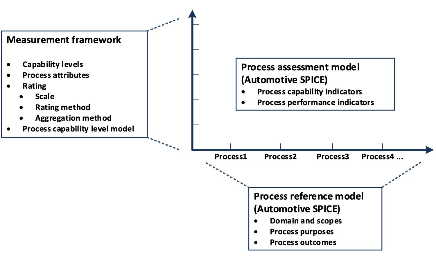
Figure 1 — Process assessment model relationship
3.1. Process reference model
Processes are collected into process groups according to the domain of activities they address.
These process groups are organized into 3 process categories: Primary life cycle processes, Organizational life cycle processes and Supporting life cycle processes.
For each process a purpose statement is formulated that contains the unique functional objectives of the process when performed in a particular environment. For each purpose statement a list of specific outcomes is associated, as a list of expected positive results of the process performance.
For the process dimension, the Automotive SPICE process reference model provides the set of processes shown in Figure 2.
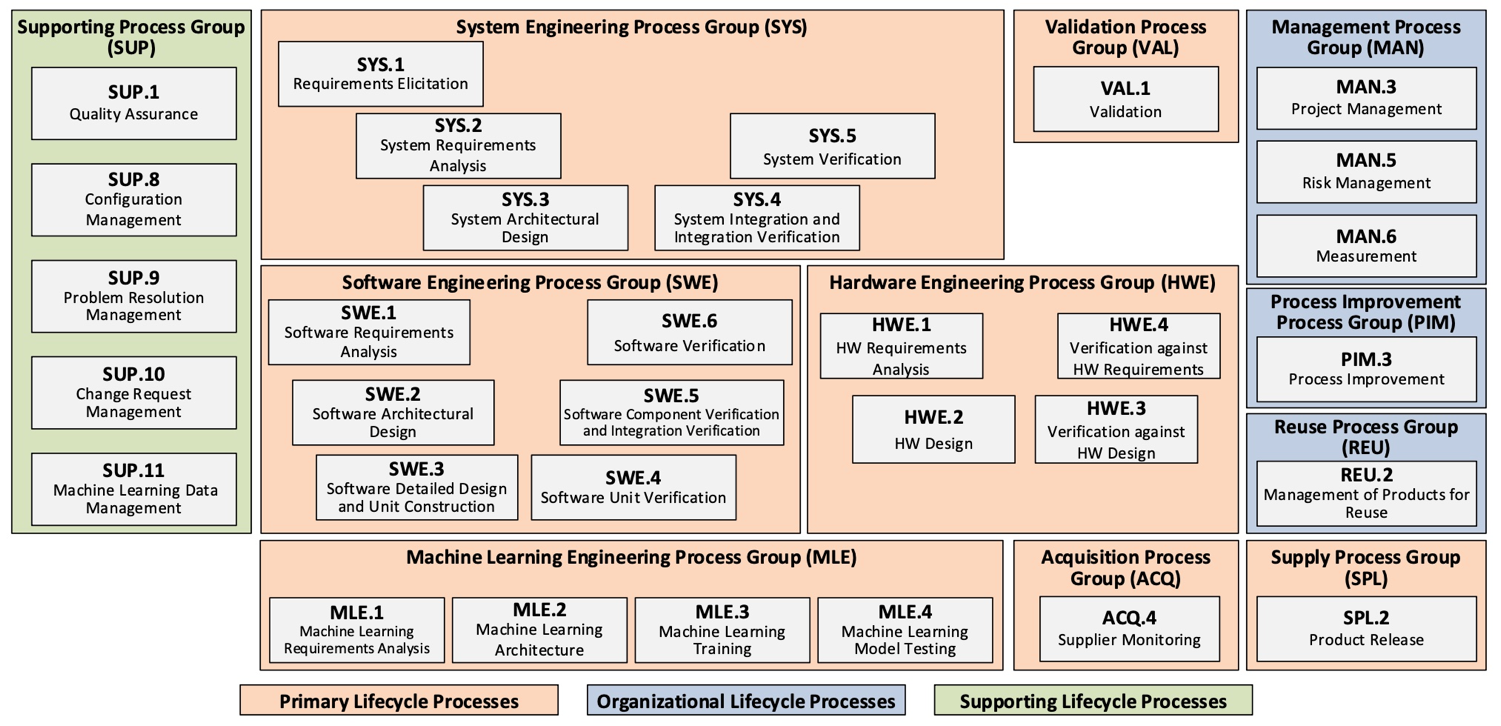
Figure 2 — Automotive SPICE process reference model – Overview
3.1.1. Primary life cycle processes category
The primary life cycle processes category consists of processes that may apply for an acquirer of products from a supplier or may apply for product development when responding to stakeholder needs and delivering products including the engineering processes needed for specification, design, implementation, integration and verification.
The primary life cycle processes category consists of the following groups:
the Acquisition process group
the Supply process group
the System engineering process group
the Validation process group
the Software engineering process group
the Machine learning engineering process group
the Hardware engineering process group
The Acquisition process group (ACQ) consists of one process that is performed by the customer, or by the supplier when acting as a customer for its own suppliers, in order to acquire a product and/or service.
ACQ.4 |
Supplier Monitoring |
The Supply process group (SPL) consists of one process performed by the supplier in order to supply a product and/or a service.
SPL.2 |
Product Release |
The System Engineering process group (SYS) consists of processes addressing the elicitation and management of customer and internal requirements, the definition of the system architecture and the integration and verification on the system level.
SYS.1 |
Requirements Elicitation |
SYS.2 |
System Requirements Analysis |
SYS.3 |
System Architectural Design |
SYS.4 |
System Integration and Integration Verification |
SYS.5 |
System Verification |
The Validation process group (VAL) consists of one process that is performed to provide evidence that the product to be delivered satisfies the expectations for its intended use.
VAL.1 |
Validation |
The Software Engineering process group (SWE) consists of processes addressing the management of software requirements derived from the system requirements, the development of the corresponding software architecture and design as well as the implementation, integration and verification of the software.
SWE.1 |
Software Requirements Analysis |
SWE.2 |
Software Architectural Design |
SWE.3 |
Software Detailed Design and Unit Construction |
SWE.4 |
Software Unit Verification |
SWE.5 |
Software Component Verification and Integration Verification |
SWE.6 |
Software Verification |
The Machine Learning Engineering process group (MLE) consists of processes addressing the management of ML requirements derived from the software requirements, the development of the corresponding ML architecture, the training of ML model, and testing of ML model against ML requirements.
MLE.1 |
Machine Learning Requirements Analysis |
MLE.2 |
Machine Learning Architecture |
MLE.3 |
Machine Learning Training |
MLE.4 |
Machine Learning Model Testing |
The Hardware Engineering process group (HWE) consists of processes addressing the management of hardware requirements derived from the system requirements, the development of the corresponding hardware architecture and design as well as the verification of the hardware.
HWE.1 |
Hardware Requirements Analysis |
HWE.2 |
Hardware Design |
HWE.3 |
Verification against Hardware Design |
HWE.4 |
Verification against Hardware Requirements |
3.1.2. Supporting life cycle processes category
The supporting life cycle processes category consists of processes that may be employed by any of the other processes at various points in the life cycle.
SUP.1 |
Quality Assurance |
SUP.8 |
Configuration Management |
SUP.9 |
Problem Resolution Management |
SUP.10 |
Change Request Management |
SUP.11 |
Machine Learning Data Management |
3.1.3. Organizational life cycle processes category
The organizational life cycle processes category consists of processes that develop process, product, and resource assets which, when used by projects in the organization, may help the organization achieve its business goals.
The organizational life cycle processes category consists of the following groups:
the Management process group;
the Process Improvement process group;
the Reuse process group.
The Management process group (MAN) consists of processes that may be used by anyone who manages any type of project or process within the life cycle.
MAN.3 |
Project Management |
MAN.5 |
Risk Management |
MAN.6 |
Measurement |
The Process Improvement process group (PIM) covers one process that contains practices to improve the processes performed in the organizational unit.
PIM.3 |
Process Improvement |
The Reuse process group (REU) covers one process to systematically exploit reuse opportunities in organization’s product portfolio.
REU.2 |
Management of Products for Reuse |
3.2. Measurement framework
The measurement framework provides the necessary requirements and rules for the capability dimension. It defines a schema which enables an assessor to determine the Capability Level of a given process. These capability levels are defined as part of the measurement framework.
To enable the rating, the measurement framework provides process attributes defining a measurable property of process capability. Each process attribute is assigned to a specific capability level. The extent of achievement of a certain process attribute is represented by means of a rating based on a defined rating scale. The rules from which an assessor can derive a final capability level for a given process are represented by a process capability level model.
Automotive SPICE defines its own measurement framework.
Note: The Automotive SPICE measurement framework is an adaption of ISO/IEC 33020:2019. Text incorporated from ISO/IEC 33020 within this chapter is written in italic font and marked with a left side bar.
3.2.1. Process capability levels and process attributes
The process capability levels, and associated process attributes are described in detail in chapter 5.
Process attributes are features of a process that can be evaluated on a scale of achievement, providing a measurement of the capability of the process. They are applicable to all processes.
A capability level is characterized by one or more process attributes whose implementation result in a significant improvement in the capability to perform a process. Each attribute addresses a specific aspect of the capability level. The levels constitute a rational way of progressing through improvement of the capability of any process.
There are six capability levels as listed in Table 14, incorporating nine process attributes:
Level 0: Incomplete process |
The process is not implemented or fails to achieve its process purpose. |
Level 1: Performed process |
The implemented process achieves its process purpose |
Level 2: Managed process |
The previously described performed process is now implemented in a managed fashion (planned, monitored and adjusted) and its work products are appropriately established, controlled and maintained. |
Level 3: Established process |
The previously described managed process is now implemented using a defined process that is capable of achieving its process outcomes. |
Level 4: Predictable process |
The previously described established process now operates predictively within defined limits to achieve its process outcomes. Quantitative management needs are identified, measurement data are collected and analyzed to identify assignable causes of variation. Corrective action is taken to address assignable causes of variation. |
Level 5: Innovating process |
The previously described predictable process is now continually improved to respond to organizational change. |
Within this process assessment model, the determination of capability is based upon the nine process attributes (PA) as listed in Table 15 — Process attributes.
Attribute ID |
Process Attributes |
|---|---|
Level 0: Incomplete process |
|
Level 1: Performed process |
|
PA 1.1 |
Process performance process attribute |
Level 2: Managed process |
|
PA 2.1 |
Performance management process attribute |
PA 2.2 |
Work product management process attribute |
Level 3: Established process |
|
PA 3.1 |
Process definition process attribute |
PA 3.2 |
Process deployment process attribute |
Level 4: Predictable process |
|
PA 4.1 |
Quantitative analysis process attribute |
PA 4.2 |
Quantitative control process attribute |
Level 5: Innovating process |
|
PA 5.1 |
Process innovation process attribute |
PA 5.2 |
Process innovation implementation process attribute |
3.2.2. Process attribute rating
To support the rating of process attributes, the measurement framework provides a defined rating scale with an option for refinement, different rating methods and different aggregation methods depending on the class of the assessment (e.g., required for organizational maturity assessments).
3.2.2.1. Rating scale
Within this process measurement framework, a process attribute is a measureable property of process capability. A process attribute rating is a judgement of the degree of achievement of the process attribute for the assessed process.
The rating scale is shown in Table 16 — Rating scale.
Note. The rating scale is identical to ISO/IEC 33020:2019
N |
Not achieved |
There is little or no evidence of achievement of the defined process attribute in the assessed process. |
P |
Partially achieved |
There is some evidence of an approach to, and some achievement of, the defined process attribute in the assessed process. Some aspects of achievement of the process attribute may be unpredictable. |
L |
Largely achieved |
There is evidence of a systematic approach to, and significant achievement of, the defined process attribute in the assessed process. Some weaknesses related to this process attribute may exist in the assessed process. |
F |
Fully achieved |
There is evidence of a complete and systematic approach to, and full achievement of, the defined process attribute in the assessed process. No significant weaknesses related to this process attribute exist in the assessed process. |
The ordinal scale defined above shall be understood in terms of percentage achievement of a process attribute. The corresponding percentages shall be:
N |
Not achieved |
0 to ≤ 15% achievement |
P |
Partially achieved |
> 15% to ≤ 50% achievement |
L |
Largely achieved |
> 50% to ≤ 85% achievement |
F |
Fully achieved |
> 85% to ≤ 100% achievement |
The ordinal scale may be further refined for the measures P and L as defined below.
P- |
Partially achieved: |
There is some evidence of an approach to, and some achievement of, the defined process attribute in the assessed process. Many aspects of achievement of the process attribute may be unpredictable. |
P+ |
Partially achieved: |
There is some evidence of an approach to, and some achievement of, the defined process attribute in the assessed process. Some aspects of achievement of the process attribute may be unpredictable. |
L- |
Largely achieved: |
There is evidence of a systematic approach to, and significant achievement of, the defined process attribute in the assessed process. Many weaknesses related to this process attribute may exist in the assessed process. |
L+ |
Largely achieved: |
There is evidence of a systematic approach to, and significant achievement of, the defined process attribute in the assessed process. Some weaknesses related to this process attribute may exist in the assessed process. |
The corresponding percentages shall be:
P- |
Partially achieved - |
> 15% to ≤ 32.5% achievement |
P+ |
Partially achieved + |
> 32.5 to ≤ 50% achievement |
L- |
Largely achieved - |
> 50% to ≤ 67.5% achievement |
L+ |
Largely achieved + |
> 67.5% to ≤ 85% achievement |
3.2.3. Rating and aggregation method
Rating and aggregation methods are taken from ISO/IEC 33020:2019, which provides the following definitions:
A process outcome is the observable result of successful achievement of the process purpose.
A process attribute outcome is the observable result of achievement of a specified process attribute.
Process outcomes and process attribute outcomes may be characterised as an intermediate step to providing a process attribute rating.
When performing rating, the rating method employed shall be specified relevant to the class of assessment. The following rating methods are defined.
The use of rating method may vary according to the class, scope and context of an assessment. The lead assessor shall decide which (if any) rating method to use. The selected rating method(s) shall be specified in the assessment input and referenced in the assessment report.
ISO/IEC 33020:2019 provides the following 3 rating methods: Rating method R1
The approach to process attribute rating shall satisfy the following conditions:
Each process outcome of each process within the scope of the assessment shall be characterized for each process instance, based on validated data;
Each process attribute outcome of each process attribute for each process within the scope of the assessment shall be characterized for each process instance, based on validated data;
Process outcome characterizations for all assessed process instances shall be aggregated to provide a process performance attribute achievement rating;
Process attribute outcome characterizations for all assessed process instances shall be aggregated to provide a process attribute achievement rating.
Rating method R2
The approach to process attribute rating shall satisfy the following conditions:
Each process attribute for each process within the scope of the assessment shall be characterized for each process instance, based on validated data;
Process attribute characterizations for all assessed process instances shall be aggregated to provide a process attribute achievement rating.
Rating method R3
Process attribute rating across assessed process instances shall be made without aggregation.
In principle the three rating methods defined in ISO/IEC 33020:2019 depend on
whether the rating is made only on process attribute level (Rating method 3 and 2) or – with more level of detail – both on process attribute and process attribute outcome level (Rating method 1); and
the type of aggregation ratings across the assessed process instances for each process
If a rating is performed for both process attributes and process attribute outcomes (Rating method 1), the result will be a process performance attribute outcome rating on level 1 and a process attribute achievement rating on higher levels.
Depending on the class, scope and context of the assessment an aggregation within one process (one-dimensional, vertical aggregation), across multiple process instances (one-dimensional, horizontal aggregation) or both (two-dimensional, matrix aggregation) is performed.
ISO/IEC 33020:2019 provides the following examples:
When performing an assessment, ratings may be summarized across one or two dimensions.
For example, when rating a
process attribute for a given process, one may aggregate ratings of the associated process (attribute) outcomes – such an aggregation will be performed as a vertical aggregation (one dimension).
process (attribute) outcome for a given process attribute across multiple process instances, one may aggregate the ratings of the associated process instances for the given process (attribute) outcome such an aggregation will be performed as a horizontal aggregation (one dimension)
process attribute for a given process, one may aggregate the ratings of all the process (attribute) outcomes for all the processes instances – such an aggregation will be performed as a matrix aggregation across the full scope of ratings (two dimensions)
The standard defines different methods for aggregation. Further information can be taken from ISO/IEC 33020:2019.
3.2.4. Process capability level model
The process capability level achieved by a process shall be derived from the process attribute ratings for that process according to the process capability level model defined in Table 20 — Capability levels.
The process capability level model defines the rules how the achievement of each level depends on the rating of the process attributes for the assessed and all lower levels.
As a general rule the achievement of a given level requires a largely or fully achievement of the corresponding process attributes and a full achievement of any lower lying process attribute.
Scale |
Process attribute |
Rating |
Level 1 |
PA 1.1: Process performance process attribute |
Largely or fully |
Level 2 |
PA 1.1: Process performance process attribute PA 2.1: Process performance management process attribute PA 2.2: Work product management process attribute |
Fully Largely or fully Largely or fully |
Level 3 |
PA 1.1: Process performance process attribute PA 2.1: Process performance management process attribute PA 2.2: Work product management process attribute PA 3.1: Process definition process attribute PA 3.2: Process deployment process attribute |
Fully Fully Fully Largely or fully Largely or fully |
Level 4 |
PA 1.1: Process performance process attribute PA 2.1: Process performance management process attribute PA 2.2: Work product management process attribute PA 3.1: Process definition process attribute PA 3.2: Process deployment process attribute PA 4.1: Quantitative analysis process attribute PA 4.2: Quantitative control process attribute |
Fully Fully Fully Fully Fully Largely or fully Largely or fully |
Level 5 |
PA 1.1: Process performance process attribute PA 2.1: Process performance management process attribute PA 2.2: Work product management process attribute PA 3.1: Process definition process attribute PA 3.2: Process deployment process attribute PA 4.1: Quantitative analysis process attribute PA 4.2: Quantitative control process attribute PA 5.1: Process innovation process attribute PA 5.2: Process innovation implementation process attribute |
Fully Fully Fully Fully Fully Fully Fully Largely or fully Largely or fully |
3.3. Process assessment model
The process assessment model offers indicators in order to identify whether the process outcomes and the process attribute outcomes (achievements) are present or absent in the instantiated processes of projects and organizational units. These indicators provide guidance for assessors in accumulating the necessary objective evidence to support judgments of capability. They are not intended to be regarded as a mandatory set of checklists to be followed.
3.3.1. Assessment indicators
According to ISO/IEC 33004, a process assessment model needs to define a set of assessment indicators:
Assessment Indicators
A process assessment model shall be based on a set of assessment indicators that:
explicitly address the purpose and process outcomes, as defined in the selected process reference model, of each of the processes within the scope of the process assessment model;
demonstrate the achievement of the process attributes within the scope of the process assessment model;
demonstrate the achievement (where relevant) of the process quality levels within the scope of the process assessment model.
The assessment indicators generally fall into three types:
practices that support achievement of either the process purpose or the specific process attribute.
information items and their characteristics that demonstrate the respective achievements.
resources and infrastructure that support the respective achievements. [ISO/IEC 33004:2015, 6.3.1]
In this assessment model, only practices and information items are used.
Practices are representing activity-oriented indicators, where information items are representing result-oriented indicators. Both practices and information items are used for judging objective evidence to be collected and accumulated in the performance of an assessment.
As a first type of assessment indicator, practices are provided, which can be divided into two types:
1. Base practices (BP), applying to capability level 1
They provide an indication of the extent of achievement of the process outcomes. Base practices relate to one or more process outcomes, thus being always process-specific and not generic.
2. Generic practices (GP), applying to capability levels 1 to 5
They provide an indication of the extent of process attribute achievement. Generic practices relate to one or more process attribute achievements, thus applying to any process.
As a second type of assessment indicators, information items (II) including their characteristics (IIC) are provided in Annex B.
These are meant to offer a good practice and state-of-the-art knowledge guide for the assessor. Therefore, information items including their characteristics are supposed to be a quickly accessible information source during an assessment.
Information item characteristics shall not be interpreted as a required structure of a corresponding work products, which is defined by the project and organization, respectively.
Please refer to chapter 3.3.2 for understanding the difference between information items and work products.
ISO 33004:2015 requires the mapping of assessment indicators to process attributes as shown in figure 3.
The capability of a process on level 1 is only characterized by the measure of the extent to which the process outcomes are achieved. According to ISO 33003:2015, a measurement framework requires each level to reveal a process attribute. Therefore, the only process performance attribute for capability Level 1 (PA.1.1) has a single generic practice (GP 1.1.1) pointing as an editorial reference to the respective process performance indicators (see figure 3 and chapter 4).
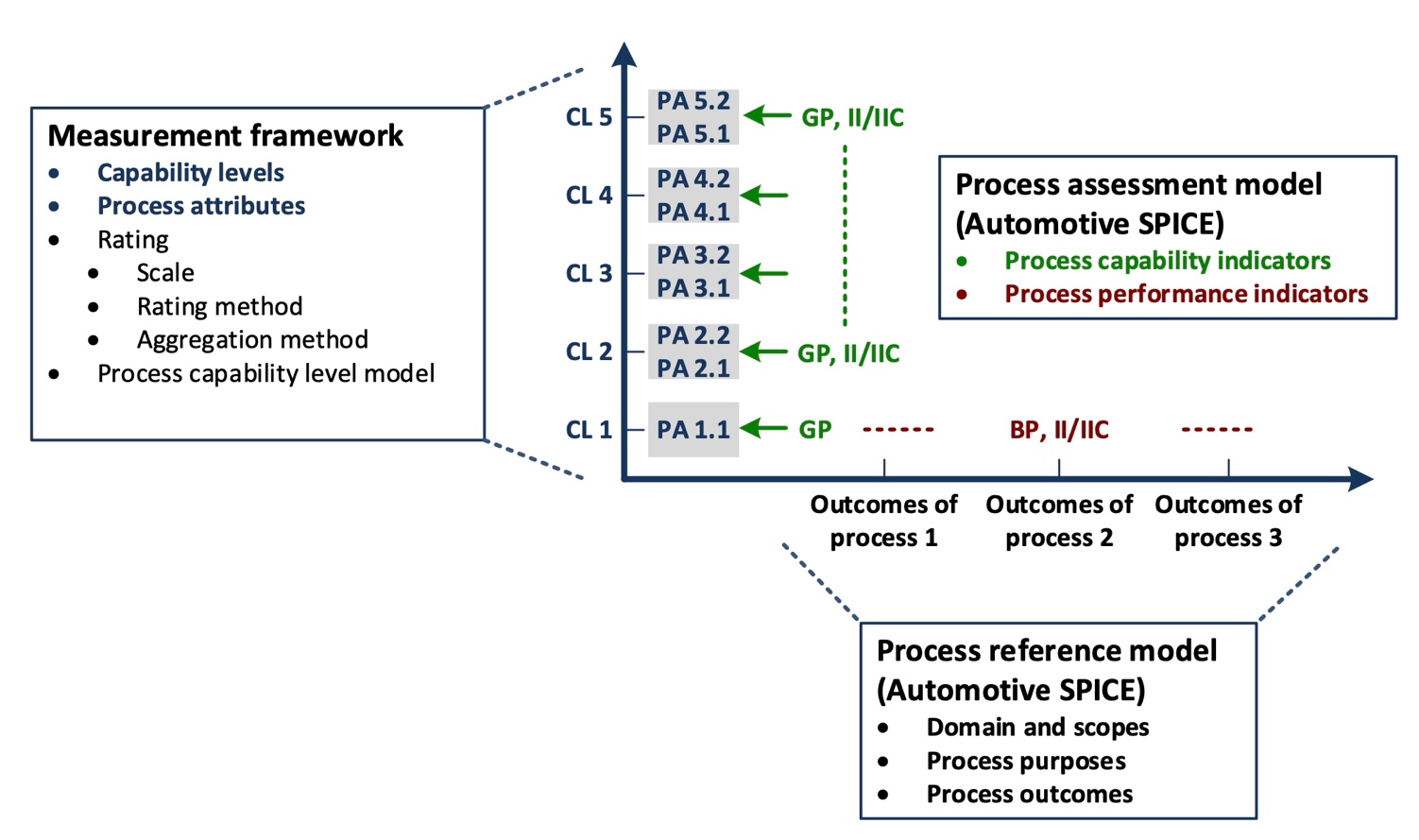
Figure 4 — Relationship between assessment indicators and process capability
The detailed mapping of base practices / indicators and generic practices / indicators to process outcomes and achievements, is provided in corresponding tables in chapter 4 and 5, respectively.
3.3.2. Understanding information Items and work products
In order to judge the presence or absence of process outcomes and process attribute achievements an assessment obtains objective evidence. All such evidence comes either from the examination of work products related to a specific output of the processes assessed, or from statements made by the performers and managers of the processes. Sources for such evidence is either repository content of the assessed processes, or testimony provided by the performers and managers of the assessed processes.
As described in chapter 3.3.1, this process assessment model provides information items serving as indicators to guide the assessor when judging a process attribute achievement.
3.3.2.1. Information items versus work products
ISO/IEC 33001 provides the following definition of the term “information item”:
information item
separately identifiable body of information that is produced, stored, and delivered for human use
Note 1 to entry: An information item can be produced in several versions during a system, software, or service life cycle. Syn: information product.
[ISO/IEC 33001:2015, 3.1.4]
Note: Human use includes the information stored, managed and processed by a tool.
One common definition of the term “work product” is:
work product
artifact resulting from the execution of a process
[ISO/IEC/IEEE 24765:2017]
Both terms are used in different context in an assessment:
Information items are defining relevant pieces of information used by the assessors to judge the achievement of process attributes.
Work products are produced by the organization assessed when performing, managing, establishing, analyzing and innovating processes.
Information items (together with their characteristics) are provided as guidance for “what to look for” when examining the work products available in the assessed organization. The extent of implementation of an information item (in line with its defined characteristics) in a related work product serves as objective evidence supporting the assessment of a particular process. A documented process and assessor judgment is needed to ensure that the process context (application domain, business purpose, development methodology, size of the organization, etc.) is considered when using this information.
Information items shall therefore not be mistaken for the work product generated by the assessed organization itself. There is no 1:1 relationship between an information item and the work product taken as sample evidence by the assessor when assessing the achievement of a process outcome and process attribute achievements. An output generated by a process may comprise multiple information item characteristics and multiple outputs may also contain the same information item characteristics.
Information item characteristics should be considered as indicators when considering whether, given the context, a work product is contributing to the intended purpose of the process. Context-sensitivity means that assessor judgment is needed to ensure that the actual context (application domain, business purpose, development methodology, size of the organization, etc.) is considered when using the information items.
3.3.2.2. Types of work products
A work product to be considered as evidence when rating a process attribute may not necessary be outputs from the processes assessed but can also be originated from other processes of the organization. Once such a work product is used in the performance of a process under assessment, it may be considered by the assessor as objective evidence.
In a lot of cases work products are comprising documentation aspects, such as specifications, reports, records, architectural designs, software code etc.
Examples of work products not comprising any documentation aspects are software binaries, raw data, or a physical electronic hardware.
3.3.3. Understanding the level of abstraction of a PAM
The term “process” can be understood at three levels of abstraction. Note that these levels of abstractions are not meant to define a strict black-or-white split, nor is it the aim to provide a scientific classification schema – the message here is to understand that, in practice, when it comes to the term “process” there are different abstraction levels, and that a PAM resides at the highest.
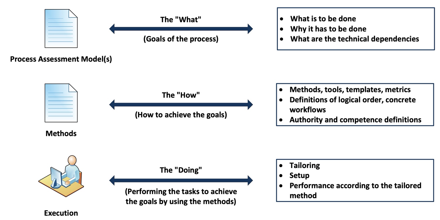
Figure 5 — Possible levels of abstraction for the term “process”
Capturing experience acquired during product development (i.e., at the DOING level) in order to share this experience with others means creating a HOW level. However, a HOW is always specific to a particular context such as a company, an organizational unit, or a product line. For example, the HOW of a project, organizational unit, or company A is potentially not applicable as is to a project, organizational unit, or company B. However, both might be expected to adhere the principles represented by PAM indicators for process outcomes and process attribute achievements. These indicators are at the WHAT level while deciding on solutions for concrete templates, proceedings, and tooling etc. is left to the HOW level.
3.3.4. Why a PRM and PAM are not a lifecycle model or development process blueprint
A lifecycle model defines phases and activities in a logical timely order, possibly including cycles or loops, and parallelization. For example, some standards such as ISO 26262 or ISO/SAE 21434 are centered around a lifecycle model (neither of these standards in fact represents a PRM according to ISO/IEC 33004). Companies, organizational units, or projects will interpret such general lifecycle models given in standards, and then detail it out into roles, organizational interactions and interfaces, tools or tool chains, work instructions, and artifacts. Lifecycle models therefore are a concept at the HOW level (see Section 3.3.3).
In contrast, a PRM/PAM according to ISO/IEC 33004 (formerly ISO/IEC 15504-2) is at the level of the WHAT by abstracting from any HOW level, see Figure 4 in Section 3.3.3. In Automotive SPICE®, this has been, and is, indicated by the process MAN.3 Project Management requiring in BP2 “Define project life cycle”. A PRM/PAM groups a set of coherent and related characteristics of a particular technical topic and calls it ‘process’. In different terms, a process in a PRM represents a ‘distinct conceptual silo’. In this respect, a PRM/PAM
neither predefines, nor discourages, any order in which PRM processes or Base Practices are to be performed. Ultimately, in Automotive SPICE consistency must be fulfilled as required by the traceability/consistency Base Practices in MAN.3 or SYS.x, SWE.x, and HWE.x;
does not predefine any particular work product structure, or work product blueprints. For example, the process SYS.2 does not mean that there shall be exactly one system requirements specification containing everything provided by the stakeholders.
As a consequence, it is the assessor’s responsibility to perform a mapping of elements in such a HOW level to the Assessment Indicators in the PAM, see Figure 5.
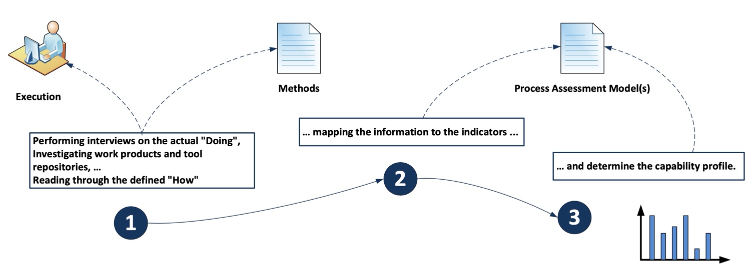
Figure 6 — Performing a process assessment for determining process capability
In this respect, a PRM or PAM further is not supposed to represent a product element hierarchy either.
4. Process reference model and performance indicators (Level 1)
The processes in the process dimension can be drawn from the Automotive SPICE process reference model, which is incorporated in the tables below indicated by a red bar at the left side.
Each table related to one process in the process dimension contains the process reference model (indicated by a red bar) and the process performance indicators necessary to define the process assessment model. The process performance indicators consist of base practices (indicated by a green bar) and output information items (indicated by a blue bar).
Process reference model |
|
The individual processes are identified with a unique process identifier and a process name. A process purpose statement is provided, and process outcomes are defined to represent the process dimension of the Automotive SPICE process reference model. The background coloring of process ID’s and names are indicating the assignment to the corresponding process group. |
Process performance indicators |
|
A set of base practices for the process providing a definition of the activities to be performed to accomplish the process purpose and fulfill the process outcomes. The base practice headers are summarized at the end of a process to demonstrate their relationship to the process outcomes. |
|
The output information items that are relevant to accomplish the process purpose and fulfill the process outcomes summarized at the end of a process to demonstrate their relationship to the process outcomes.
|
4.1. Acquisition process group (ACQ)
4.1.1. ACQ.4 Supplier Monitoring
Process ID |
ACQ.4 |
Process name |
Supplier Monitoring |
Process purpose |
The purpose is to track and assess the performance of an external contract-based supplier company against agreed commitments. |
Process outcomes |
|
Base Practices |
|---|
ACQ.4.BP1: Agree on and maintain joint activities, joint interfaces, and information to be exchanged. Establish and maintain an agreement on information to be exchanged, on joint activities, joint interfaces, responsibilities, type and frequency of joint activities, communications, meetings, status reports, and reviews. |
ACQ.4.BP2: Exchange all agreed information. Use the defined joint interfaces between customer and supplier for the exchange of all agreed information. |
ACQ.4.BP3: Review development work products with the supplier. Review development work products with the supplier on the agreed regular basis, covering technical aspects, problems and risks. Track open measures.
|
ACQ.4.BP4: Review progress of the supplier. Review progress of the supplier regarding schedule, quality, and cost on the agreed regular basis. Track open measures to closure and perform risk mitigation activities.
|
ACQ.4.BP5: Act to correct deviations. Take action when agreed objectives are not achieved. Negotiate changes to objectives and document them in the agreements. |
ACQ.4 Supplier Monitoring |
Outcome 1 |
Outcome 2 |
Outcome 3 |
Outcome 4 |
|---|---|---|---|---|
Output Information Items |
||||
02-01 Commitment/Agreement |
X |
X |
X |
X |
13-52 Communication evidence |
X |
X |
X |
|
13-09 Meeting support evidence |
X |
X |
||
13-14 Progress status |
X |
X |
||
13-16 Change request |
X |
|||
13-19 Review evidence |
X |
|||
14-02 Corrective action |
X |
|||
15-51 Analysis results |
X |
|||
Base Practices |
||||
BP1: Agree on and maintain joint processes, joint interfaces, and information to be exchanged |
X |
X |
X |
|
BP2: Exchange all agreed information |
X |
X |
X |
|
BP3: Review development work products with the supplier |
X |
X |
X |
|
BP4: Review progress of the supplier |
X |
X |
X |
|
BP5: Act to correct deviations |
X |
X |
4.2. Supply process group (SPL)
4.2.1. SPL.2 Product Release
Process ID |
|---|
SPL.2 |
Process name |
Product Release |
Process purpose |
The purpose is to control the release of a product to the intended customer. |
Process outcomes |
|
Base Practices |
|---|
SPL.2.BP1: Define the functional content of releases. Define the functionality to be included and the release criteria for each release.
|
SPL.2.BP2: Define release package. Define the release as well as supporting tools and information.
|
SPL.2.BP3: Ensure unique identification of releases. Ensure a unique identification of the release based upon the intended purpose and expectations of the release.
|
SPL.2.BP4: Build the release from items under configuration control. Build the release from items under configuration control to ensure integrity.
|
SPL.2.BP5: Ensure release approval before delivery. Criteria for the release are satisfied before delivery takes place. |
SPL.2.BP6: Provide a release note. A release is accompanied by information detailing key characteristics of the release.
|
SPL2.BP7: Communicate the type, service level and duration of support for a release. Identify and communicate the type, service level and duration of support for a release. |
SPL.2.BP8: Deliver the release package to the intended customer. Deliver the release package to the intended customer.
|
SPL.2 Product Release |
Outcome 1 |
Outcome 2 |
Outcome 3 |
Outcome 4 |
Outcome 5 |
|---|---|---|---|---|---|
Output Information Items |
|||||
11-03 Release note |
X |
X |
X |
X |
|
11-04 Product release package |
X |
X |
|||
13-06 Delivery evidence |
X |
X |
|||
13-13 Product release approval |
X |
X |
|||
18-06 Product release criteria |
X |
X |
X |
||
Base Practices |
|||||
BP1: Define the functional content of releases |
X |
||||
BP2: Define release package |
X |
||||
BP3: Establish a product release classification and numbering scheme |
X |
||||
BP4: Build the release from configured items |
X |
||||
BP5: Ensure product release approval before delivery |
X |
||||
BP6: Provide a release note |
X |
X |
|||
BP7: Communicate the type, service level and duration of support for a release |
X |
X |
|||
BP8: Deliver the release package to the intended customer |
X |
4.3. System engineering process group (SYS)
4.3.1. SYS.1 Requirements Elicitation
Process ID |
|---|
SYS.1 |
Process name |
Requirements Elicitation |
Process purpose |
The purpose is to gather, analyze, and track evolving stakeholder needs and requirements throughout the lifecycle of the product and/or service to establish a set of agreed requirements. |
Process outcomes |
|
Base Practices |
|---|
SYS.1.BP1: Obtain stakeholder expectations and requests. Obtain and define stakeholder expectations and requests through direct solicitation of stakeholder input, and through review of stakeholder business proposals (where relevant) and other documents containing inputs to stakeholder requirements, and consideration of the target operating and hardware environment.
|
SYS.1.BP2: Agree on requirements. Formalize the stakeholder’s expectations and requests into requirements. Reach a common understanding of the set of stakeholder requirements among affected parties by obtaining an explicit agreement from all affected parties.
|
SYS.1.BP3: Analyze stakeholder requirements changes. Analyze all changes made to the stakeholder requirements against the agreed stakeholder requirements. Assess the impact and risks, and initiate appropriate change control and mitigation actions.
|
SYS.1.BP4: Communicate requirements status. Ensure all affected parties can be aware of the status and disposition of their requirements including changes and can communicate necessary information and data. |
SYS.1 Requirements Elicitation |
Outcome 1 |
Outcome 2 |
Outcome 3 |
Outcome 4 |
|---|---|---|---|---|
Output Information Items |
||||
15-51 Analysis Results |
X |
|||
13-52 Communication Evidence |
X |
X |
||
17-00 Requirement |
X |
|||
17-54 Requirement Attribute |
X |
X |
X |
|
Base Practices |
||||
BP1: Obtain stakeholder expectations and requests |
X |
|||
BP2: Agree on requirements |
X |
|||
BP3: Analyze stakeholder requirements changes |
X |
|||
BP4: Communicate requirements status |
X |
X |
4.3.2. SYS.2 System Requirements Analysis
Process ID |
|---|
SYS.2 |
Process name |
System Requirements Analysis |
Process purpose |
The purpose is to establish a structured and analyzed set of system requirements consistent with the stakeholder requirements. |
Process outcomes |
|
Base Practices |
|---|
SYS.2.BP1: Specify system requirements. Use the stakeholder requirements to identify and document the functional and non-functional requirements for the system according to defined characteristics for requirements.
|
SYS.2.BP2: Structure system requirements. Structure and prioritize the system requirements.
|
SYS.2.BP3: Analyze system requirements. Analyze the specified system requirements including their interdependencies to ensure correctness, technical feasibility, and to support project management regarding project estimates.
|
SYS.2.BP4: Analyze the impact on the system context. Analyze the impact that the system requirements will have on elements in the relevant system context. |
SYS.2.BP5: Ensure consistency and establish bidirectional traceability. Ensure consistency and establish bidirectional traceability between system requirements and stakeholder requirements.
|
SYS.2.BP6: Communicate agreed system requirements and impact on the system context. Communicate the agreed system requirements, and results of the impact analysis on the system context, to all affected parties. |
SYS.2 System Requirements Analysis |
Outcome 1 |
Outcome 2 |
Outcome 3 |
Outcome 4 |
Outcome 5 |
Outcome 6 |
|---|---|---|---|---|---|---|
Output Information Items |
||||||
17-00 Requirement |
X |
X |
||||
17-54 Requirement Attribute |
X |
X |
||||
15-51 Analysis Results |
X |
X |
||||
13-51 Consistency Evidence |
X |
|||||
13-52 Communication Evidence |
X |
|||||
Base Practices |
||||||
BP1: Specify system requirements |
X |
|||||
BP2: Structure system requirements |
X |
|||||
BP3: Analyze system requirements |
X |
|||||
BP4: Analyze the impact on the system context |
X |
|||||
BP5: Ensure consistency and establish bidirectional traceability |
X |
|||||
BP6: Communicate agreed system requirements and impact on the system context |
X |
4.3.3. SYS.3 System Architectural Design
Process ID |
|---|
SYS.3 |
Process name |
System Architectural Design |
Process purpose |
The purpose is to establish an analyzed system architecture, comprising static and dynamic aspects, consistent with the system requirements. |
Process outcomes |
|
Base Practices |
|---|
SYS.3.BP1: Specify static aspects of the system architecture. Specify and document the static aspects of the system architecture with respect to the functional and non-functional system requirements, including external interfaces and a defined set of system elements with their interfaces and relationships. |
SYS.3.BP2: Specify dynamic aspects of the system architecture. Specify and document the dynamic aspects of the system architecture with respect to the functional and non-functional system requirements including the behavior of the system elements and their interaction in different system modes.
|
SYS.3.BP3: Analyze system architecture. Analyze the system architecture regarding relevant technical design aspects related to the product lifecycle, and to support project management regarding project estimates, and derive special characteristics for non-software system elements. Document a rationale for the system architectural design decisions.
|
SYS.3.BP4: Ensure consistency and establish bidirectional traceability. Ensure consistency and establish bidirectional traceability between the elements of the system architecture and the system requirements that represent properties or characteristics of the physical end product.
|
SYS.3.BP5: Communicate agreed system architecture. Communicate the agreed system architecture, including the special characteristics, to all affected parties. |
SYS.3 System Architectural Design |
Outcome 1 |
Outcome 2 |
Outcome 3 |
Outcome 4 |
|---|---|---|---|---|
Output Information Items |
||||
04-06 System Architecture |
X |
|||
13-51 Consistency Evidence |
X |
|||
13-52 Communication Evidence |
X |
|||
15-51 Analysis Results |
X |
|||
17-57 Special Characteristics |
X |
|||
Base Practices |
||||
BP1: Specify static aspects of system architecture |
X |
|||
BP2: Specify dynamic aspects of system architecture |
X |
|||
BP3: Analyze the system architecture |
X |
|||
BP4: Ensure consistency and establish bidirectional traceability |
X |
|||
BP5: Communicate agreed system architecture |
X |
4.3.4. SYS.4 System Integration and Integration Verification
Process ID |
|---|
SYS.4 |
Process name |
System Integration and Integration Verification |
Process purpose |
The purpose is to integrate systems elements and verify that the integrated system elements are consistent with the system architecture. |
Process outcomes |
|
Base Practices |
|---|
SYS.4.BP1: Specify verification measures for system integration. Specify the verification measures, based on a defined sequence and preconditions for the integration of system elements against the system static and dynamic aspects of the system architecture, including
|
SYS.4.BP2: Select verification measures. Document the selection of verification measures for each integration step considering selection criteria including criteria for regression verification. The documented selection of verification measures shall have sufficient coverage according to the release scope.
|
SYS.4.BP3: Integrate system elements and perform integration verification. Integrate the system elements until the system is fully integrated according to the specified interfaces and interactions between the system elements, and according to the defined sequence and defined preconditions. Perform the selected system integration verification measures. Record the verification measure data including pass/fail status and corresponding verification measure data.
|
SYS.4.BP4: Ensure consistency and establish bidirectional traceability. Ensure consistency and establish bidirectional traceability between verification measures and the system architecture. Establish bidirectional traceability between verification results and verification measures.
|
SYS.4.BP5: Summarize and communicate results. Summarize the system integration and integration verification results and communicate them to all affected parties.
|
SYS.4 System Integration and Integration Verification |
Outcome 1 |
Outcome 2 |
Outcome 3 |
Outcome 4 |
Outcome 5 |
Outcome 6 |
Outcome 7 |
|---|---|---|---|---|---|---|---|
Output Information Items |
|||||||
08-60 Verification Measure |
X |
||||||
06-50 Integration Sequence Instruction |
X |
||||||
03-50 Verification Measure Data |
X |
||||||
08-58 Verification Measure Selection Set |
X |
||||||
15-52 Verification Results |
X |
||||||
13-51 Consistency Evidence |
X |
X |
|||||
13-52 Communication Evidence |
X |
||||||
11-06 Integrated System |
X |
||||||
Base Practices |
|||||||
BP1: Specify verification measures for system integration |
X |
||||||
BP2: Select verification measures |
X |
||||||
BP3: Integrate system elements and perform integration verification. |
X |
X |
|||||
BP4: Ensure consistency and establish bidirectional traceability |
X |
X |
|||||
BP5: Summarize and communicate results |
X |
4.3.5. SYS.5 System Verification
Process ID |
|---|
SYS.5 |
Process name |
System Verification |
Process purpose |
The purpose is to ensure that the system is verified to be consistent with the system requirements. |
Process outcomes |
|
Base Practices |
|---|
SYS.5.BP1: Specify verification measures for system verification. Specify the verification measures for system verification suitable to provide evidence for compliance with the functional and non-functional information in the system requirements, including
|
SYS.5.BP2: Select verification measures. Document the selection of verification measures considering selection criteria including criteria for regression verification. The selection of verification measures shall have sufficient coverage according to the release scope.
|
SYS.5.BP3: Perform verification of the integrated system. Perform the verification of the integrated system using the selected verification measures. Record the verification results including pass/fail status and corresponding verification measure data.
|
SYS.5.BP4: Ensure consistency and establish bidirectional traceability. Ensure consistency and establish bidirectional traceability between verification measures and system requirements. Establish bidirectional traceability between verification results and verification measures.
|
SYS.5.BP5: Summarize and communicate results. Summarize the system verification results and communicate them to all affected parties.
|
SYS.5 System Verification |
Outcome 1 |
Outcome 2 |
Outcome 3 |
Outcome 4 |
Outcome 5 |
Outcome 6 |
|---|---|---|---|---|---|---|
Output Information Item |
||||||
08-60 Verification Measure |
X |
|||||
03-50 Verification Measure Data |
X |
|||||
08-58 Verification Measure Selection Set |
X |
|||||
15-52 Verification Results |
X |
|||||
13-51 Consistency Evidence |
X |
X |
||||
13-52 Communication Evidence |
X |
|||||
Base Practices |
||||||
BP1: Specify verification measures for system verification |
X |
|||||
BP2: Select verification measures |
X |
|||||
BP3: Perform verification of the integrated system |
X |
|||||
BP4: Ensure consistency and establish bidirectional traceability. |
X |
X |
||||
BP5: Summarize and communicate results |
X |
4.4. Software engineering process group (SWE)
4.4.1. SWE.1 Software Requirements Analysis
Process ID |
|---|
SWE.1 |
Process name |
Software Requirements Analysis |
Process purpose |
The purpose is to establish a structured and analyzed set of software requirements consistent with the system requirements, and the system architecture. |
Process outcomes |
|
Base Practices |
|---|
SWE.1.BP1: Specify software requirements. Use the system requirements and the system architecture to identify and document the functional and non-functional requirements for the software according to defined characteristics for requirements.
|
SWE.1.BP2: Structure software requirements. Structure and prioritize the software requirements.
|
SWE.1.BP3: Analyze software requirements. Analyze the specified software requirements including their interdependencies to ensure correctness, technical feasibility, and to support project management regarding project estimates.
|
SWE.1.BP4: Analyze the impact on the operating environment. Analyze the impact that the software requirements will have on elements in the operating environment. |
SWE.1.BP5: Ensure consistency and establish bidirectional traceability. Ensure consistency and establish bidirectional traceability between software requirements and system architecture. Ensure consistency and establish bidirectional traceability between software requirements and system requirements.
|
SWE.1.BP6: Communicate agreed software requirements and impact on the operating environment. Communicate the agreed software requirements, and the results of the analysis of impact on the operating environment, to all affected parties. |
SWE.1 Software Requirements Analysis |
Outcome 1 |
Outcome 2 |
Outcome 3 |
Outcome 4 |
Outcome 5 |
Outcome 6 |
Outcome 7 |
|---|---|---|---|---|---|---|---|
Output Information Items |
|||||||
17-00 Requirement |
X |
X |
|||||
17-54 Requirement Attribute |
X |
||||||
15-51 Analysis Results |
X |
X |
|||||
13-51 Consistency Evidence |
X |
X |
|||||
13-52 Communication Evidence |
X |
||||||
Base Practices |
|||||||
BP1: Specify software requirements |
X |
||||||
BP2: Structure software requirements |
X |
||||||
BP3: Analyze software requirements |
X |
||||||
BP4: Analyze the impact on the operating environment |
X |
||||||
BP5: Ensure consistency and establish bidirectional traceability |
X |
X |
|||||
BP6: Communicate agreed software requirements and impact on the operating environment |
X |
4.4.2. SWE.2 Software Architectural Design
Process ID |
|---|
SWE.2 |
Process name |
Software Architectural Design |
Process purpose |
The purpose is to establish an analyzed software architecture, comprising static and dynamic aspects, consistent with the software requirements. |
Process outcomes |
|
Base Practices |
|---|
SWE.2.BP1: Specify static aspects of the software architecture. Specify and document the static aspects of the software architecture with respect to the functional and non-functional software requirements, including external interfaces and a defined set of software components with their interfaces and relationships.
|
SWE.2.BP2: Specify dynamic aspects of the software architecture. Specify and document the dynamic aspects of the software architecture with respect to the functional and nonfunctional software requirements, including the behavior of the software components and their interaction in different software modes, and concurrency aspects.
|
SWE.2.BP3: Analyze software architecture. Analyze the software architecture regarding relevant technical design aspects and to support project management regarding project estimates. Document a rationale for the software architectural design decision.
|
SWE.2.BP4: Ensure consistency and establish bidirectional traceability. Ensure consistency and establish bidirectional traceability between the software architecture and the software requirements.
|
SWE.2.BP5: Communicate agreed software architecture. Communicate the agreed software architecture to all affected parties. |
SWE.2 Software Architectural Design |
Outcome 1 |
Outcome 2 |
Outcome 3 |
Outcome 4 |
|---|---|---|---|---|
Output Information Items |
||||
04-04 Software Architecture |
X |
|||
13-51 Consistency Evidence |
X |
|||
13-52 Communication Evidence |
X |
|||
15-51 Analysis Results |
X |
|||
Base Practices |
||||
BP1: Specify static aspects of software architecture |
X |
|||
BP2: Specify dynamic aspects of software architecture |
X |
|||
BP3: Analyze software architecture |
X |
|||
BP4: Ensure consistency and establish bidirectional traceability |
X |
|||
BP5: Communicate agreed software architecture |
X |
4.4.3. SWE.3 Software Detailed Design and Unit Construction
Process ID |
|---|
SWE.3 |
Process name |
Software Detailed Design and Unit Construction |
Process purpose |
The purpose is to establish a software detailed design, comprising static and dynamic aspects, consistent with the software architecture, and to construct software units consistent with the software detailed design. |
Process outcomes |
|
Base Practices |
|---|
SWE.3.BP1: Specify the static aspects of the detailed design. For each software component specify the behavior of its software units, their static structure and relationships, their interfaces including
|
SWE.3.BP2: Specify dynamic aspects of the detailed design. Specify and document the dynamic aspects of the detailed design with respect to the software architecture, including the interactions between relevant software units to fulfill the component’s dynamic behavior.
|
SWE.3.BP3: Develop software units. Develop and document the software units consistent with the detailed design, and according to coding principles.
|
SWE.3.BP4: Ensure consistency and establish bidirectional traceability. Ensure consistency and establish bidirectional traceability between the software detailed design and the software architecture. Ensure consistency and establish bidirectional traceability between the developed software units and the software detailed design. Ensure consistency and establish traceability between the software detailed design and the software requirements.
|
SWE.3.BP5: Communicate agreed software detailed design and developed software units. Communicate the agreed software detailed design and developed software units to all affected parties. |
SWE.3 Software Detailed Design and Unit Construction |
Outcome 1 |
Outcome 2 |
Outcome 3 |
Outcome 4 |
|---|---|---|---|---|
Output Information Items |
||||
04-05 Software Detailed Design |
X |
|||
11-05 Software Unit |
X |
|
||
13-51 Consistency Evidence |
X |
|||
13-52 Communication Evidence |
X |
|||
Base Practices |
||||
BP1: Specify the static aspects of the detailed design |
X |
|||
BP2: Specify the dynamic aspects of the detailed design |
X |
|||
BP3: Develop software units |
X |
|||
BP4: Ensure consistency and establish bidirectional traceability |
X |
|||
BP5: Communicate agreed software detailed design and developed software units |
X |
4.4.4. SWE.4 Software Unit Verification
Process ID |
|---|
SWE.4 |
Process name |
Software Unit Verification |
Process purpose |
The purpose is to verify that software units are consistent with the software detailed design. |
Process outcomes |
|
Base Practices |
|---|
SWE.4.BP1: Specify software unit verification measures. Specify verification measures for each software unit defined in the software detailed design, including
|
SWE.4.BP2: Select software unit verification measures. Document the selection of verification measures considering selection criteria including criteria for regression verification. The documented selection of verification measures shall have sufficient coverage according to the release scope. |
SWE.4.BP3: Verify software units. Perform software unit verification using the selected verification measures. Record the verification results including pass/fail status and corresponding verification measure data.
|
SWE.4.BP4: Ensure consistency and establish bidirectional traceability. Ensure consistency and establish bidirectional traceability between verification measures and the software units defined in the detailed design. Establish bidirectional traceability between the verification results and the verification measures.
|
SWE.4.BP5: Summarize and communicate results. Summarize the results of software unit verification and communicate them to all affected parties.
|
SWE.4 Software Unit Verification |
Outcome 1 |
Outcome 2 |
Outcome 3 |
Outcome 4 |
Outcome 5 |
|---|---|---|---|---|---|
Output Information Items |
|||||
08-60 Verification Measure |
X |
||||
03-50 Verification Measure Data |
X |
||||
08-58 Verification Measure Selection Set |
X |
||||
15-52 Verification Results |
X |
||||
13-51 Consistency Evidence |
X |
||||
13-52 Communication Evidence |
X |
||||
Base Practices |
|||||
BP1: Specify software unit verification measures |
X |
||||
BP2: Select software unit verification measures |
X |
||||
BP3: Verify software units |
X |
||||
BP4: Ensure consistency and establish bidirectional traceability for software unit verification |
X |
||||
BP5: Summarize and communicate results |
X |
4.4.5. SWE.5 Software Component Verification and Integration Verification
Process ID |
|---|
SWE.5 |
Process name |
Software Component Verification and Integration Verification |
Process purpose |
The purpose is to verify that software components are consistent with the software architectural design, and to integrate software elements and verify that the integrated software elements are consistent with the software architecture and software detailed design. |
Process outcomes |
|
Base Practices |
|---|
SWE.5.BP1: Specify software integration verification measures. Specify verification measures, based on a defined sequence and preconditions for the integration of software elements, against the defined static and dynamic aspects of the software architecture, including
|
SWE.5.BP2: Specify verification measures for verifying software component behavior. Specify verification measures for software component verification against the defined software components’ behavior and their interfaces in the software architecture, including
|
SWE.5.BP3: Select verification measures. Document the selection of integration verification measures for each integration step considering selection criteria including criteria for regression verification. The documented selection of verification measures shall have sufficient coverage according to the release scope.
|
SWE.5.BP4: Integrate software elements and perform integration verification. Integrate the software elements until the software is fully integrated according to the specified interfaces and interactions between the Software elements, and according to the defined sequence and defined preconditions. Perform the selected integration verification measures. Record the verification measure data including pass/fail status and corresponding verification measure data.
|
SWE.5.BP5: Perform software component verification. Perform the selected verification measures for verifying software component behavior. Record the verification results including pass/fail status and corresponding verification measure data.
|
SWE.5.BP6: Ensure consistency and establish bidirectional traceability. Ensure consistency and establish bidirectional traceability between verification measures and the static and dynamic aspects of the software architecture and detailed design. Establish bidirectional traceability between verification results and verification measures.
|
SWE.5.BP7: Summarize and communicate results. Summarize the software component verification and the software integration verification results and communicate them to all affected parties.
|
SWE.5 Software Component Verification and Integration Verification |
Outcome 1 |
Outcome 2 |
Outcome 3 |
Outcome 4 |
Outcome 5 |
Outcome 6 |
Outcome 7 |
Outcome 8 |
|---|---|---|---|---|---|---|---|---|
Output Information Items |
||||||||
08-60 Verification Measure |
X |
X |
||||||
06-50 Integration Sequence Instruction |
X |
|||||||
03-50 Verification Measure Data |
X |
|||||||
08-58 Verification Measure Selection Set |
X |
|||||||
15-52 Verification Results |
X |
X |
||||||
13-51 Consistency Evidence |
X |
|||||||
13-52 Communication Evidence |
X |
|||||||
01-03 Software Component |
X |
|||||||
01-50 Integrated Software |
X |
|||||||
Base Practices |
||||||||
BP1: Specify software integration verification measures |
X |
|||||||
BP2: Specify verification measures for verifying software component behavior |
X |
|||||||
BP3: Select verification measures |
X |
|||||||
BP4: Integrate software elements and perform integration verification |
X |
X |
||||||
BP5: Perform software component verification |
X |
|||||||
BP6: Ensure consistency and establish bidirectional traceability |
X |
|||||||
BP7: Summarize and communicate results |
X |
4.4.6. SWE.6 Software Verification
Process ID |
|---|
SWE.6 |
Process name |
Software Verification |
Process purpose |
The purpose of the Software Verification process is to ensure that the integrated software is verified to be consistent with the software requirements. |
Process outcomes |
|
Base Practices |
|---|
SWE.6.BP1: Specify verification measures for software verification. Specify the verification measures for software verification suitable to provide evidence for compliance of the integrated software with the functional and non-functional information in the software requirements, including
|
SWE.6.BP2: Select verification measures. Document the selection of verification measures considering selection criteria including criteria for regression verification. The documented selection of verification measures shall have sufficient coverage according to the release scope.
|
SWE.6.BP3: Verify the integrated software. Perform the verification of the integrated software using the selected verification measures. Record the verification results including pass/fail status and corresponding verification measure data.
|
SWE.6.BP4: Ensure consistency and establish bidirectional traceability. Ensure consistency and establish bidirectional traceability between verification measures and software requirements. Establish bidirectional traceability between verification results and verification measures.
|
SWE.6.BP5: Summarize and communicate results. Summarize the software verification results and communicate them to all affected parties.
|
SWE.6 Software Verification |
Outcome 1 |
Outcome 2 |
Outcome 3 |
Outcome 4 |
Outcome 5 |
|---|---|---|---|---|---|
Output Information Items |
|||||
08-60 Verification Measure |
X |
||||
03-50 Verification Measure Data |
X |
||||
08-58 Verification Measure Selection Set |
X |
||||
15-52 Verification Results |
X |
||||
13-51 Consistency Evidence |
X |
||||
13-52 Communication Evidence |
X |
||||
Base Practices |
|||||
BP1: Specify verification measures for software verification |
X |
||||
BP2: Select verification measures |
X |
||||
BP3: Verify the integrated software |
X |
||||
BP4: Ensure consistency and establish bidirectional traceability. |
X |
||||
BP5: Summarize and communicate results |
X |
4.5. Validation process group (VAL)
4.5.1. VAL.1 Validation
Process ID |
|---|
VAL.1 |
Process name |
Validation |
Process purpose |
The purpose is to provide evidence that the end product, allowing direct end user interaction, satisfies the intended use expectations in its operational target environment. |
Process outcomes |
|
Base Practices |
|---|
VAL.1.BP1: Specify validation measures for product validation. Specify the validation measures for the end product based on the stakeholder requirements to provide evidence that it fulfills its intended use expectations in its operational target environment, and
|
VAL.1.BP2: Select validation measures. Document the selection of validation measures considering selection criteria including criteria for regression validation. The documented selection of validation measures shall have sufficient coverage according to the release scope.
|
VAL.1.BP3: Perform validation and evaluate results. Perform the validation of the integrated end product using the selected validation measures. Record the validation results including pass/fail status. Evaluate the validation results.
|
VAL.1.BP4: Ensure consistency and establish bidirectional traceability. Ensure consistency and establish bidirectional traceability from validation measures to the stakeholder requirements from which they are derived. Establish bidirectional traceability between validation results and validation measures.
|
VAL.1.BP5: Summarize and communicate results. Summarize the validation results and communicate them to all affected parties.
|
VAL.1 Validation |
Outcome 1 |
Outcome 2 |
Outcome 3 |
Outcome 4 |
|---|---|---|---|---|
Output Information Items |
||||
08-59 Validation Measure |
X |
|||
08-57 Validation Measure Selection Set |
X |
|||
13-24 Validation Results |
X |
|||
13-51 Consistency Evidence |
X |
|||
13-52 Communication Evidence |
X |
|||
Base Practices |
||||
BP1: Specify validation measures |
X |
|||
BP2: Select validation measures |
X |
|||
BP3: Perform validation and evaluate results |
X |
|||
BP4: Ensure consistency and establish traceability. |
X |
|||
BP5: Summarize and communicate results |
X |
4.6. Machine Learning Engineering process group (MLE)
4.6.1. MLE.1 Machine Learning Requirements Analysis
Process ID |
|---|
MLE.1 |
Process name |
Machine Learning Requirements Analysis |
Process purpose |
The purpose is to refine the machine learning-related software requirements into a set of ML requirements. |
Process outcomes |
|
Base Practices |
|---|
MLE.1.BP1: Specify ML requirements. Use the software requirements and the software architecture to identify and specify functional and non-functional ML requirements, as well as ML data requirements specifying data characteristics (e.g., gender, weather conditions, street conditions within the ODD) and their expected distributions.
|
MLE.1.BP2: Structure ML requirements. Structure and prioritize the ML requirements.
|
MLE.1.BP3: Analyze ML requirements. Analyze the specified ML requirements including their interdependencies to ensure correctness, technical feasibility, and ability for machine learning model testing, and to support project management regarding project estimates.
|
MLE.1.BP4: Analyze the impact on the ML operating environment. Analyze the impact that the ML requirements will have on interfaces of software components and the ML operating environment.
|
MLE.1.BP5: Ensure consistency and establish bidirectional traceability. Ensure consistency and establish bidirectional traceability between ML requirements and software requirements and between ML requirements and the software architecture.
|
MLE.1.BP6: Communicate agreed ML requirements and impact on the operating environment. Communicate the agreed ML requirements, and the results of the impact analysis on the ML operating environment to all affected parties. |
MLE.1 Machine Learning Requirements Analysis |
Outcome 1 |
Outcome 2 |
Outcome 3 |
Outcome 4 |
Outcome 5 |
Outcome 6 |
|---|---|---|---|---|---|---|
Output Information Items |
||||||
17-00 Requirement |
X |
X |
||||
17-54 Requirement attribute |
X |
X |
||||
13-52 Communication evidence |
X |
|||||
13-51 Consistency evidence |
X |
|||||
15-51 Analysis results |
X |
X |
||||
Base Practices |
||||||
BP1: Specify ML requirements |
X |
|||||
BP2: Structure ML requirements |
X |
|||||
BP3: Analyze ML requirements |
X |
|||||
BP4: Analyze the impact on the ML operating environment |
X |
|||||
BP5: Ensure consistency and establish bidirectional traceability |
X |
|||||
BP6: Communicate agreed ML requirements |
X |
4.6.2. MLE.2 Machine Learning Architecture
Process ID |
|---|
MLE.2 |
Process name |
Machine Learning Architecture |
Process purpose |
The purpose is to establish an ML architecture supporting training and deployment, consistent with the ML requirements, and to evaluate the ML architecture against defined criteria. |
Process outcomes |
|
Base Practices |
|---|
MLE.2.BP1: Develop ML architecture. Develop and document the ML architecture that specifies ML architectural elements including details of the ML model, pre- and postprocessing, and hyperparameters which are required to create, train, test, and deploy the ML model.
|
MLE.2.BP2: Determine hyperparameter ranges and initial values. Determine and document the hyperparameter ranges and the initial values as a basis for the training. |
MLE.2.BP3: Analyze ML architectural elements. Define criteria for analysis of the ML architectural elements. Analyze ML architectural elements according to the defined criteria.
|
MLE.2.BP4: Define interfaces of the ML architectural elements. Determine and document the internal and external interfaces of each ML architectural element including its interfaces to related software components. |
MLE.2.BP5: Define resource consumption objectives for the ML architectural elements. Determine and document the resource consumption objectives for all relevant ML architectural elements during training and deployment. |
MLE.2.BP6: Ensure consistency and establish bidirectional traceability. Ensure consistency and establish bidirectional traceability between the ML architectural elements and the ML requirements.
|
MLE.2.BP7: Communicate agreed ML architecture. Inform all affected parties about the agreed ML architecture including the details of the ML model and the initial hyperparameter values. |
MLE.2 Machine Learning Architecture |
Outcome 1 |
Outcome 2 |
Outcome 3 |
Outcome 4 |
Outcome 5 |
Outcome 6 |
Outcome 7 |
|---|---|---|---|---|---|---|---|
Output Information Items |
|||||||
04-51 ML architecture |
X |
X |
X |
X |
X |
||
13-52 Communication evidence |
X |
||||||
13-51 Consistency evidence |
X |
||||||
01-54 Hyperparameter |
X |
X |
|||||
15-51 Analysis results |
X |
X |
|||||
Base Practices |
|||||||
BP1: Develop ML architecture |
X |
||||||
BP2: Determine hyperparameter ranges and initial values. |
X |
||||||
BP3: Evaluate ML architectural elements |
X |
||||||
BP4: Define interfaces of the ML architectural elements |
X |
||||||
BP5: Define resource consumption objectives for the ML architectural elements |
X |
||||||
BP6: Ensure consistency and establish bidirectional traceability |
X |
||||||
BP7: Communicate agreed ML architecture |
X |
4.6.3. MLE.3 Machine Learning Training
Process ID |
|---|
MLE.3 |
Process name |
Machine Learning Training |
Process purpose |
The purpose is to optimize the ML model to meet the defined ML requirements. |
Process outcomes |
|
Base Practices |
|---|
MLE.3.BP1: Specify ML training and validation approach. Specify an approach which supports the training and validation of the ML model to meet the defined ML requirements. The ML training and validation approach includes
|
MLE.3.BP2: Create ML training and validation data set. Select data from the ML data collection provided by SUP.11 and assign them to the data set for training and validation of the ML model according to the specified ML training and validation approach.
|
MLE.3.BP3: Create and optimize ML model. Create the ML model according to the ML architecture and train it, using the identified ML training and validation data set according to the ML training and validation approach to meet the defined ML requirements, and training and validation exit criteria. |
MLE.3.BP4: Ensure consistency and establish bidirectional traceability. Ensure consistency and establish bidirectional traceability between the ML training and validation data set and the ML data requirements.
|
MLE.3.BP5: Summarize and communicate agreed trained ML model. Summarize the results of the optimization and inform all affected parties about the agreed trained ML model. |
MLE.3 Machine Learning Training |
Outcome 1 |
Outcome 2 |
Outcome 3 |
Outcome 4 |
Outcome 5 |
|---|---|---|---|---|---|
Output Information Items |
|||||
08-65 ML training and validation approach |
X |
||||
03-51 ML data set |
X |
||||
01-53 Trained ML model |
X |
||||
01-54 Hyperparameter |
X |
||||
13-51 Consistency evidence |
X |
||||
13-52 Communication evidence |
X |
||||
Base Practices |
|||||
BP1: Specify ML training and validation approach |
X |
||||
BP2: Create ML training and validation data set |
X |
||||
BP3: Create and optimize ML model |
X |
||||
BP4: Ensure consistency and establish bidirectional traceability |
X |
||||
BP5: Summarize and communicate agreed trained ML model |
X |
4.6.4. MLE.4 Machine Learning Model Testing
Process ID |
|---|
MLE.4 |
Process name |
Machine Learning Model Testing |
Process purpose |
The purpose is to ensure compliance of the trained ML model and the deployed ML model with the ML requirements. |
Process outcomes |
|
Base Practices |
|---|
MLE.4.BP1: Specify an ML test approach. Specify an ML test approach suitable to provide evidence for compliance of the trained ML model and the deployed ML model with the ML requirements. The ML test approach includes
|
MLE.4.BP2: Create ML test data set. Create the ML test data set needed for testing of the trained ML model and testing of the deployed ML model from the ML data collection provided by SUP.11 considering the ML test approach. The ML test data set shall not be used for training.
|
MLE.4.BP3: Test trained ML model. Test the trained ML model according to the ML test approach using the created ML test data set. Record and evaluate the ML test results.
|
MLE.4.BP4: Derive deployed ML model. Derive the deployed ML model from the trained ML model according to the ML architecture. The deployed ML model shall be used for testing and delivery to software integration.
|
MLE4.BP5: Test deployed ML model. Test the deployed ML model according to the ML test approach using the created ML test data set. Record and evaluate the ML test results. |
MLE.4.BP6: Ensure consistency and establish bidirectional traceability. Ensure consistency and establish bidirectional traceability between the ML test approach and the ML requirements, and the ML test data set and the ML data requirements; and bidirectional traceability is established between the ML test approach and ML test results.
|
MLE.4.BP7: Summarize and communicate results. Summarize the ML test results of the ML model. Inform all affected parties about the agreed results and the deployed ML model. |
MLE.4 Machine Learning Model Testing |
Outcome 1 |
Outcome 2 |
Outcome 3 |
Outcome 4 |
Outcome 5 |
Outcome 6 |
|---|---|---|---|---|---|---|
Output Information Items |
||||||
08-64 ML test approach |
X |
|||||
03-51 ML data set |
X |
|||||
13-50 ML test results |
X |
X |
||||
11-50 Deployed ML model |
X |
|||||
13-51 Consistency evidence |
X |
|||||
13-52 Communication evidence |
X |
|||||
Base Practices |
||||||
BP1: Specify an ML test approach |
X |
|||||
BP2: Create ML test data set |
X |
|||||
BP3: Test trained ML model |
X |
|||||
BP4: Derive deployed ML model |
X |
|||||
BP5: Test deployed ML model |
X |
|||||
BP6: Ensure consistency and establish bidirectional traceability |
X |
|||||
BP7: Summarize and communicate results |
X |
4.7. Hardware Engineering process group (HWE)
4.7.1. HWE.1 Hardware Requirements Analysis
Process ID |
|---|
HWE.1 |
Process name |
Hardware Requirements Analysis |
Process purpose |
The purpose is to establish a structured and analyzed set of hardware requirements consistent with the system requirements, and the system architectural design. |
Process outcomes |
|
Base Practices |
|---|
HWE.1.BP1: Specify hardware requirements. Use the system requirements, and the system architecture including interface definitions, to identify and document the functional and nonfunctional requirements of the hardware according to defined characteristics for requirements.
|
HWE.1.BP2: Structure hardware requirements. Structure and prioritize the hardware requirements.
|
HWE.1.BP3: Analyze hardware requirements. Analyze the specified hardware requirements including their interdependencies to ensure correctness, technical feasibility, and to support project management regarding project estimates.
|
HWE.1.BP4: Analyze the impact on the operating environment. Identify the interfaces between the specified hardware and other elements of the operating environment. Analyze the impact that the hardware requirements will have on these interfaces and the operating environment. |
HWE.1.BP5: Ensure consistency and establish bidirectional traceability. Ensure consistency and establish traceability between hardware requirements and the system architecture. Ensure consistency and establish traceability between hardware requirements and system requirements.
|
HWE.1.BP6: Communicate agreed hardware requirements and impact on the operating environment. Communicate the agreed hardware requirements and results of the analysis of impact on the operating environment to all affected parties. |
HWE.1 Hardware Requirements Analysis |
Outcome 1 |
Outcome 2 |
Outcome 3 |
Outcome 4 |
Outcome 5 |
Outcome 6 |
Outcome 7 |
|---|---|---|---|---|---|---|---|
Output Information Items |
|||||||
13-52 Communication Evidence |
X |
||||||
13-51 Consistency Evidence |
X |
X |
|||||
17-00 Requirement |
X |
X |
X |
||||
17-54 Requirement Attribute |
X |
||||||
15-51 Analysis Results |
X |
X |
|||||
Base Practices |
|||||||
BP1: Specify hardware requirements |
X |
||||||
BP2: Structure hardware requirements |
X |
||||||
BP3: Analyze hardware requirements |
X |
||||||
BP4: Analyze the impact on the operating environment |
X |
||||||
BP5: Ensure consistency and establish bidirectional traceability |
X |
X |
|||||
BP6: Communicate agreed hardware requirements |
X |
4.7.2. HWE.2 Hardware Design
Process ID |
|---|
HWE.2 |
Process name |
Hardware Design |
Process purpose |
The purpose is to provide an analyzed design, including dynamic aspects, that is consistent with the hardware requirements and suitable for manufacturing, and to derive production-relevant data. |
Process outcomes |
|
Base Practices |
|---|
HWE.2.BP1: Specify the hardware architecture. Develop the hardware architecture that identifies the hardware components. Document the rationale for the defined hardware architecture.
|
HWE.2.BP2: Specify the hardware detailed design. Based on components identified in the hardware architecture, specify the detailed design description and the schematics for the intended hardware variants, including the interfaces between the hardware elements. Derive the hardware layout, the hardware bill of materials, and the production data.
|
HWE.2.BP3: Specify dynamic aspects. Evaluate and document the dynamic behavior of the relevant hardware elements and the interaction between them.
|
HWE.2.BP4: Analyze the hardware architecture and the hardware detailed design. Analyze the hardware architecture and hardware detailed design regarding relevant technical aspects, and support project management regarding project estimates. Identify special characteristics.
|
HWE.2.BP5: Ensure consistency and establish bidirectional traceability. Ensure consistency and establish traceability between hardware elements and hardware requirements. Ensure consistency and establish traceability between the hardware detailed design and components of the hardware architecture.
|
HWE.2.BP6: Communicate agreed hardware architecture and hardware detailed design. Communicate the agreed hardware architecture and the hardware detailed design, including the special characteristics and relevant production data, to all affected parties. |
HWE.2 Hardware Design |
Outcome 1 |
Outcome 2 |
Outcome 3 |
Outcome 4 |
Outcome 5 |
Outcome 6 |
|---|---|---|---|---|---|---|
Output Information Items |
||||||
04-52 Hardware Architecture |
X |
|||||
04-53 Hardware Detailed Design |
X |
|||||
15-51 Analysis Results |
X |
|||||
13-51 Consistency Evidence |
X |
|||||
17-57 Special Characteristics |
X |
|||||
13-52 Communication Evidence |
X |
|||||
04-54 Hardware Schematics |
X |
X |
X |
|||
14-54 Hardware Bill of Materials |
X |
X |
X |
|||
04-55 Hardware Layout |
X |
X |
X |
|||
03-54 Hardware Production Data |
X |
X |
X |
|||
04-56 Hardware Element Interface |
X |
|||||
Base Practices |
||||||
BP1: Specify the hardware architecture |
X |
X |
X |
|||
BP2: Specify the hardware detailed design |
X |
X |
X |
|||
BP3: Specify dynamic aspects |
X |
|||||
BP4: Analyze the hardware architecture and the hardware detailed design |
X |
|||||
BP5: Ensure consistency and establish bidirectional traceability |
X |
|||||
BP7: Communicate agreed hardware architecture and hardware detailed design |
X |
X |
X |
4.7.3. HWE.3 Verification against Hardware Design
Process ID |
|---|
HWE.3 |
Process name |
Verification against Hardware Design |
Process purpose |
The purpose is to ensure that the production data compliant hardware is verified to provide evidence for compliance with the hardware design. |
Process outcomes |
1) Verification measures are specified for verification of the hardware against the hardware design, including the interfaces between hardware elements and the dynamic aspects. 2) Verification measures are selected according to the release scope considering criteria, including criteria for regression verification. 3) Verification is performed on production data compliant samples using the selected verification measures, and verification results are recorded. 4) Consistency and bidirectional traceability are established between hardware elements and verification measures. 5) Bidirectional traceability is established between verification measures and verification results.
|
Base Practices |
|---|
HWE.3.BP1: Specify verification measures for the verification against hardware design. Specify the verification measures suitable to provide evidence for compliance of the hardware with the hardware design and its dynamic aspects. This includes
|
HWE.3.BP2: Ensure use of compliant samples. Ensure that the samples used for verification against hardware design are compliant with the corresponding production data, including special characteristics. Ensure that deviations are documented and that they do not alter verification results.
|
HWE.3.BP3: Select verification measures. Document the selection of verification measures considering selection criteria including regression criteria. The documented selection of verification measures shall have sufficient coverage according to the release scope.
|
HWE.3.BP4: Verify hardware design. Verify the hardware design using the selected verification measures. Record the verification results including pass/fail status and corresponding verification measure output data.
|
HWE.3.BP5: Ensure consistency and establish bidirectional traceability. Ensure consistency and establish bidirectional traceability between hardware elements and the verification measures. Establish bidirectional traceability between the verification measures and verification results.
|
HWE.3.BP6: Summarize and communicate results. Summarize the verification results and communicate them to all affected parties.
|
HWE.3 Verification against Hardware Design |
Outcome 1 |
Outcome 2 |
Outcome 3 |
Outcome 4 |
Outcome 5 |
Outcome 6 |
|---|---|---|---|---|---|---|
Output Information Items |
||||||
08-60 Verification Measure |
X |
|||||
03-50 Verification Measure Data |
X |
|||||
08-58 Verification Measure Selection Set |
X |
|||||
15-52 Verification Results |
X |
|||||
13-51 Consistency Evidence |
X |
X |
||||
13-52 Communication Evidence |
X |
|||||
Base Practices |
||||||
BP1: Specify verification measures for the verification against hardware design |
X |
|||||
BP2: Ensure use of compliant samples |
X |
|||||
BP3: Select verification measures |
X |
|||||
BP4: Verify hardware design |
X |
|||||
BP5: Ensure consistency and establish bidirectional traceability |
X |
X |
||||
BP6: Summarize and communicate results |
X |
4.7.4. HWE.4 Verification against Hardware Requirements
Process ID |
|---|
HWE.4 |
Process name |
Verification against Hardware Requirements |
Process purpose |
The purpose is to ensure that the complete hardware is verified to be consistent with the hardware requirements. |
Process outcomes |
|
Base Practices |
|---|
HWE.4.BP1: Specify verification measures for the verification against hardware requirements. Specify the verification measure to provide evidence for compliance with the hardware requirements. This includes
|
HWE.4.BP2: Ensure use of compliant samples. Ensure that the samples used for the verification against hardware requirements are compliant with the corresponding production data, including special characteristics, provided by hardware design.
|
HWE.4.BP3: Select verification measures. Document the selection of verification measures considering selection criteria including regression criteria. The documented selection of verification measures shall have sufficient coverage according to the release scope.
|
HWE.4.BP4: Verify the compliant hardware samples. Verify the compliant hardware samples using the selected verification measures. Record the verification results including pass/fail status and corresponding verification measure output data.
|
HWE.4.BP5: Ensure consistency and establish bidirectional traceability. Ensure consistency between hardware requirements and verification measures. Establish bidirectional traceability between hardware requirements and verification measures. Establish bidirectional traceability between verification measures and verification results.
|
HWE.4.BP6: Summarize and communicate results. Summarize the verification results and communicate them to all affected parties.
|
HWE.4 Verification against Hardware Requirements |
Outcome 1 |
Outcome 2 |
Outcome 3 |
Outcome 4 |
Outcome 5 |
Outcome 6 |
|---|---|---|---|---|---|---|
Output Information Items |
||||||
08-60 Verification Measure |
X |
|||||
03-50 Verification Measure Data |
X |
|||||
08-58 Verification Measure Selection Set |
X |
|||||
15-52 Verification Results |
X |
|||||
13-51 Consistency Evidence |
X |
X |
||||
13-52 Communication Evidence |
X |
|||||
Base Practices |
||||||
BP1: Specify verification measures for the verification against hardware requirements |
X |
|||||
BP2: Ensure use of compliant samples |
X |
|||||
BP3: Select verification measures |
X |
|||||
BP4: Verify hardware |
X |
|||||
BP5: Ensure consistency and establish bidirectional traceability |
X |
X |
||||
BP6: Summarize and communicate results |
X |
4.8. Supporting process group (SUP)
4.8.1. SUP.1 Quality Assurance
Process ID |
|---|
SUP.1 |
Process name |
Quality Assurance |
Process purpose |
The purpose of the Quality Assurance Process is to provide independent and objective assurance that work products and processes comply with defined criteria and that nonconformances are resolved and further prevented. |
Process outcomes |
|
Base Practices |
|---|
SUP.1.BP1: Ensure independence of quality assurance. Ensure that quality assurance is performed independently and objectively without conflicts of interest.
|
SUP.1.BP2: Define criteria for quality assurance. Define quality criteria for work products as well as for process tasks and their performance.
|
SUP.1.BP3: Assure quality of work products. Identify work products subject to quality assurance according to the quality criteria. Perform appropriate activities to evaluate the work products against the defined quality criteria and document the results.
|
SUP.1.BP4: Assure quality of process activities. Identify processes subject to quality assurance according to the quality criteria. Perform appropriate activities to evaluate the processes against their defined quality criteria and associated target values and document the results.
|
SUP.1.BP5: Summarize and communicate quality assurance activities and results. Regularly report performance, non-conformances, and trends of quality assurance activities to all affected parties. |
SUP.1.BP6: Ensure resolution of non-conformances. Analyze, track, correct, resolve, and further prevent non-conformances found in quality assurance activities.
|
SUP.1.BP7: Escalate non-conformances. Escalate relevant non-conformances to appropriate levels of management and other relevant stakeholders to facilitate their resolution.
|
SUP.1 Quality Assurance |
Outcome 1 |
Outcome 2 |
Outcome 3 |
Outcome 4 |
Outcome 5 |
Outcome 6 |
|---|---|---|---|---|---|---|
Output Information Items |
||||||
16-50 Organizational structure |
X |
X |
||||
18-52 Escalation path |
X |
X |
||||
18-07 Quality criteria |
X |
X |
X |
|||
13-52 Communication evidence |
X |
X |
X |
|||
13-18 Quality conformance evidence |
X |
X |
||||
13-19 Review evidence |
X |
X |
||||
14-02 Corrective action |
X |
X |
||||
Base Practices |
||||||
BP1: Ensure independence of quality assurance. |
X |
|||||
BP2: Define criteria for quality assurance. |
X |
|||||
BP3: Assure quality of work products. |
X |
X |
||||
BP4: Assure quality of process activities. |
X |
X |
||||
BP5: Summarize and communicate quality assurance activities and results. |
X |
X |
X |
|||
BP6: Ensure resolution of non-conformances. |
X |
X |
||||
BP7: Escalate non-conformances. |
X |
X |
4.8.2. SUP.8 Configuration Management
Process ID |
|---|
SUP.8 |
Process name |
Configuration Management |
Process purpose |
The purpose of the Configuration Management Process is to establish and maintain the integrity of relevant configuration items and baselines, and make them available to affected parties. |
Process outcomes |
|
Base Practices |
|---|
SUP.8.BP1: Identify configuration items. Define selection criteria for identifying relevant work products to be subject to configuration management. Identify and document configuration items according to the defined selection criteria.
|
SUP.8.BP2: Define configuration item properties. Define the necessary properties needed for the modification and control of configuration items.
|
SUP.8.BP3: Establish configuration management. Establish configuration management mechanisms for control of identified configuration items including the configuration item properties, including mechanisms for controlling parallel modifications of configuration items.
|
SUP.8.BP4: Control modifications. Control modifications using the configuration management mechanisms.
|
SUP.8.BP5: Establish baselines. Define and establish baselines for internal purposes, and for external product delivery, for all relevant configuration items. |
SUP.8.BP6: Summarize and communicate configuration status. Record, summarize, and communicate the status of configuration items and established baselines to affected parties in order to support the monitoring of progress and status.
|
SUP.8.BP7: Ensure completeness and consistency. Ensure that the information about configuration items is correct and complete including configuration item properties. Ensure the completeness and consistency of baselines.
|
SUP.8.BP8: Verify backup and recovery mechanisms availability. Verify the availability of appropriate backup and recovery mechanisms for the configuration management including the controlled configuration items. Initiate measures in case of insufficient backup and recovery mechanisms.
|
SUP.8 Configuration Management |
Outcome 1 |
Outcome 2 |
Outcome 3 |
Outcome 4 |
Outcome 5 |
Outcome 6 |
Outcome 7 |
Outcome 8 |
|---|---|---|---|---|---|---|---|---|
Output Information Items |
||||||||
18-53 Configuration item selection criteria |
X |
|||||||
01-52 Configuration item list |
X |
X |
X |
|||||
16-03 Configuration management system |
X |
X |
X |
|||||
13-08 Baseline |
X |
X |
||||||
14-01 Change history |
X |
X |
X |
|||||
15-56 Configuration status |
X |
|||||||
13-51 Consistency Evidence |
X |
|||||||
06-52 Backup and recovery mechanism information |
X |
|||||||
Base Practices |
||||||||
BP1: Identify configuration items |
X |
|||||||
BP2: Define configuration item properties |
X |
|||||||
BP3: Establish configuration management |
X |
X |
||||||
BP4: Control modifications |
X |
|||||||
BP5: Establish baselines |
X |
|||||||
BP6: Summarize and communicate configuration status |
X |
|||||||
BP7: Ensure completeness and consistency |
X |
|||||||
BP8: Verify backup and recovery mechanisms availability |
X |
4.8.3. SUP.9 Problem Resolution Management
Process ID |
|---|
SUP.9 |
Process name |
Problem Resolution Management |
Process purpose |
The purpose of the Problem Resolution Management Process is to ensure that problems are identified, recorded, analyzed, and their resolution is managed and controlled. |
Process outcomes |
|
Base Practices |
|---|
SUP.9.BP1: Identify and record the problem. Each problem is uniquely identified, described and recorded. A status is assigned to each problem to facilitate tracking. Supporting information is provided to reproduce and diagnose the problem.
|
SUP.9.BP2: Determine the cause and the impact of the problem. Analyze the problem, determine its cause, including common causes if existing, and impact. Involve relevant parties. Categorize the problem.
|
SUP.9.BP3: Authorize urgent resolution action. Obtain authorization for immediate action if a problem requires an urgent resolution according to the categorization. |
SUP.9.BP4: Raise alert notifications. If according to the categorization the problem has a high impact on other systems or other affected parties, an alert notification needs to be raised accordingly. |
SUP.9.BP5: Initiate problem resolution. Initiate appropriate actions according to the categorization to resolve the problem long-term, including review of those actions or initiate a change request. This includes synchronization and consistency with short-term urgent resolution actions, if applicable. |
SUP.9.BP6: Track problems to closure. Track the status of problems to closure including all related change requests. The closure of problems is accepted by relevant stakeholders. |
SUP.9.BP7: Report the status of problem resolution activities. Collect and analyze problem resolution management data, identify trends, and initiate related actions. Regularly report the results of data analysis, the identified trends and the status of problem resolution activities to relevant stakeholders.
|
SUP.9 Problem Resolution Management |
Outcome 1 |
Outcome 2 |
Outcome 3 |
Outcome 4 |
Outcome 5 |
|---|---|---|---|---|---|
Output Information Items |
|||||
13-07 Problem |
X |
X |
X |
X |
|
15-55 Problem analysis evidence |
X |
||||
15-12 Problem status |
X |
||||
Base Practices |
|||||
BP1: Identify and record the problem |
X |
X |
|||
BP2: Determine the cause and the impact of the problem |
X |
X |
|||
BP3: Authorize urgent resolution action |
X |
||||
BP4: Raise alert notifications |
X |
||||
BP5: Initiate problem resolution |
X |
||||
BP6: Track problems to closure |
X |
X |
|||
BP7: Report the status of problem resolution activities |
X |
4.8.4. SUP.10 Change Request Management
Process ID |
|---|
SUP.10 |
Process name |
Change Request Management |
Process purpose |
The purpose of the Change Request Management Process is to ensure that change requests are recorded, analyzed, tracked, approved, and implemented. |
Process outcomes |
|
Base Practices |
|---|
SUP.10.BP1: Identify and record the change requests. The scope for application of change requests is identified. Each change request is uniquely identified, described, and recorded, including the initiator and reason of the change request. A status is assigned to each change request to facilitate tracking.
|
SUP.10.BP2: Analyze and assess change requests. Change requests are analyzed by relevant parties according to analysis criteria. Work products affected by the change request and dependencies to other change requests are determined. The impact of the change requests is assessed.
|
SUP.10.BP3: Approve change requests before implementation. Change requests are prioritized and approved for implementation based on analysis results and availability of resources.
|
SUP.10.BP4: Establish bidirectional traceability. Establish bidirectional traceability between change requests and work products affected by the change requests. In case that the change request is initiated by a problem, establish bidirectional traceability between change requests and the corresponding problem reports. |
SUP.10.BP5: Confirm the implementation of change requests. The implementation of change requests is confirmed before closure by relevant stakeholders. |
SUP.10.BP6: Track change requests to closure. Change requests are tracked to closure. The status of change requests is communicated to all affected parties.
|
SUP.10 Change Request Management |
Outcome 1 |
Outcome 2 |
Outcome 3 |
Outcome 4 |
Outcome 5 |
Outcome 6 |
|---|---|---|---|---|---|---|
Output Information Items |
||||||
18-57 Change analysis criteria |
X |
|||||
13-16 Change request |
X |
X |
X |
X |
X |
|
13-51 Consistency evidence |
X |
|||||
Base Practices |
||||||
BP1: Identify and record the change requests |
X |
|||||
BP2: Analyze and assess change requests |
X |
|||||
BP3: Approve change requests before implementation |
X |
|||||
BP4: Establish bidirectional traceability |
X |
|||||
BP5: Confirm the implementation of change requests |
X |
|||||
BP6: Track change requests to closure |
X |
4.8.5. SUP.11 Machine Learning Data Management
Process ID |
|---|
SUP.11 |
Process name |
Machine Learning Data Management |
Process purpose |
The purpose is to define and align ML data with ML data requirements, maintain the integrity and quality of the ML data, and make them available to affected parties. |
Process outcomes |
|
Base Practices |
|---|
SUP.11.BP1: Establish an ML data management system. Establish an ML data management system which supports
|
SUP.11.BP2: Develop an ML data quality approach. Develop an approach to ensure that the quality of ML data is analyzed based on defined ML data quality criteria and activities are performed to support avoidance of biases of data.
|
SUP.11.BP3: Collect ML data. Relevant sources for raw data are identified and continuously monitored for changes. The raw data is collected according to the ML data requirements.
|
SUP.11.BP4: Process ML data. The raw data are processed (annotated, analyzed, and structured) according to the ML data requirements. |
SUP.11.BP5: Assure quality of ML data. Perform the activities according to the ML data quality approach to ensure that the ML data meets the defined ML data quality criteria.
|
SUP.11.BP6: Communicate agreed processed ML data. Inform all affected parties about the agreed processed ML data and provide them to the affected parties. |
SUP.11 Machine Learning Data Management |
Outcome 1 |
Outcome 2 |
Outcome 3 |
Outcome 4 |
Outcome 5 |
|---|---|---|---|---|---|
Output Information Items |
|||||
16-52 ML data management system |
X |
||||
19-50 ML data quality approach |
X |
||||
03-53 ML data |
X |
X |
|||
13-52 Communication evidence |
X |
||||
Base Practices |
|||||
BP1: Establish an ML data management system |
X |
||||
BP2: Develop an ML data quality approach |
X |
||||
BP3: Collect ML data |
X |
||||
BP4: Process ML data |
X |
||||
BP5: Assure quality of ML data |
X |
||||
BP6: Communicate agreed processed ML data |
X |
4.9. Management process group (MAN)
4.9.1. MAN.3 Project Management
Process ID |
|---|
MAN.3 |
Process name |
Project Management |
Process purpose |
The purpose is to identify and control the activities, and establish resources necessary for a project to develop a product, in the context of the project’s requirements and constraints. |
Process outcomes |
|
Base Practices |
|---|
MAN.3.BP1: Define the scope of work. Identify the project’s goals, motivation and boundaries. |
MAN.3.BP2: Define project life cycle. Define the life cycle for the project, which is appropriate to the scope, context, and complexity of the project. Define a release scope for relevant milestones.
|
MAN.3.BP3: Evaluate feasibility of the project. Evaluate the feasibility of achieving the goals of the project with respect to time, project estimates, and available resources.
|
MAN.3.BP4: Define and monitor work packages. Define and monitor work packages and their dependencies according to defined project life cycle and estimations.
|
MAN.3.BP5: Define and monitor project estimates and resources. Define and monitor project estimates of effort and resources based on project’s goals, project risks, motivation and boundaries.
|
MAN.3.BP6: Define and monitor required skills, knowledge, and experience. Identify and monitor the required skills, knowledge, and experience for the project in line with the estimates and work packages.
|
MAN.3.BP7: Define and monitor project interfaces and agreed commitments. Identify and agree interfaces of the project with affected stakeholders and monitor agreed commitments. Define an escalation mechanism for commitments that are not fulfilled.
|
MAN.3.BP8: Define and monitor project schedule. Allocate resources to work packages and schedule each activity of the project. Monitor the performance of activities against schedule. |
MAN.3.BP9: Ensure consistency. Regularly adjust estimates, resources, skills, work packages and their dependencies, schedules, plans, interfaces, and commitments for the project to ensure consistency with the scope of work.
|
MAN.3.BP10: Review and report progress of the project. Regularly review and report the status of the project and the fulfillment of work packages against estimated effort and duration to all affected parties. Prevent recurrence of identified problems.
|
MAN.3 Project Management |
Outcome 1 |
Outcome 2 |
Outcome 3 |
Outcome 4 |
Outcome 5 |
Outcome 6 |
Outcome 7 |
|---|---|---|---|---|---|---|---|
Output Information Items |
|||||||
08-53 Scope of work |
X |
||||||
08-54 Feasibility analysis |
X |
X |
|||||
14-10 Work package |
X |
X |
X |
||||
13-52 Communication evidence |
X |
X |
|||||
13-16 Change request |
X |
||||||
13-51 Consistency evidence |
X |
X |
|||||
14-02 Corrective action |
X |
X |
|||||
18-52 Escalation path |
X |
X |
X |
||||
08-56 Schedule |
X |
X |
X |
||||
14-50 Stakeholder groups list |
X |
||||||
15-06 Project status |
X |
X |
|||||
Base Practices |
|||||||
BP1: Define the scope of work |
X |
||||||
BP2: Define project life cycle |
X |
X |
|||||
BP3: Evaluate feasibility of the project |
X |
||||||
BP4: Define and monitor work packages |
X |
X |
X |
X |
|||
BP5: Define and monitor project estimates and resources |
X |
X |
X |
||||
BP6: Define and monitor required skills, knowledge, and experience |
X |
X |
|||||
BP7: Define and monitor project interfaces and agreed commitments |
X |
X |
X |
||||
BP8: Define and monitor project schedule |
X |
X |
|||||
BP9: Ensure consistency |
X |
X |
X |
X |
|||
BP10: Review and report progress of the project |
X |
X |
4.9.2. MAN.5 Risk Management
Process ID |
|---|
MAN.5 |
Process name |
Risk Management |
Process purpose |
The purpose is to Regularly identify, analyze, treat and monitor process related risks and product related risks. |
Process outcomes |
|
Base Practices |
|---|
MAN.5.BP1: Identify sources of risks. Identify and regularly update the sources of risks with affected parties.
|
MAN.5.BP2: Identify potential undesirable events. Identify potential undesirable events within the scope of the risk management for the project. |
MAN.5.BP3: Determine risks. Determine the probability and severity of the undesirable events to support priorities for the mitigation of the risks.
|
MAN.5.BP4: Define risk treatment options. For each risk select a treatment option to accept, mitigate, avoid, or share (transfer) the risk. |
MAN.5.BP5: Define and perform risk treatment activities. Define and perform risk activities for risk treatment options. |
MAN.5.BP6: Monitor risks. Regularly re-evaluate the risk related to the identified potential undesirable events to determine changes in the status of a risk and to evaluate the progress of the risk treatment activities.
|
MAN.5.BP7: Take corrective action. When risk treatment activities are not effective, take appropriate corrective action.
|
MAN.5 Risk Management |
Outcome 1 |
Outcome 2 |
Outcome 3 |
Outcome 4 |
Outcome 5 |
|---|---|---|---|---|---|
Output Information Items |
|||||
15-51 Analysis results |
X |
X |
X |
X |
|
15-09 Risk status |
X |
X |
X |
X |
|
08-55 Risk measure |
X |
X |
|||
14-02 Corrective action |
X |
X |
|||
Base Practices |
|||||
BP1: Identify sources of risks |
X |
||||
BP2: Identify potential undesirable events |
X |
||||
BP3: Determine risks |
X |
||||
BP4: Define risk treatment options |
X |
X |
|||
BP5: Define and perform risk treatment activities. |
X |
X |
|||
BP6: Monitor risks |
X |
||||
BP7: Take corrective action |
X |
4.9.3. MAN.6 Measurement
Process ID |
|---|
MAN.6 |
Process name |
Measurement |
Process purpose |
The purpose is to Collect and analyze data relating to the development results and processes implemented within the organization and its projects, to support effective management of the processes. |
Process outcomes |
|
Base Practices |
|---|
MAN.6.BP1: Identify information needs. Identify the measurement information needs that are necessary to evaluate the achievement of process objectives and work products.
|
MAN.6.BP2: Specify metrics. Identify and develop an appropriate set of metrics based on measurement information needs.
|
MAN.6.BP3: Collect and store metrics. Collect and store both base and derived metrics, including any context information necessary to verify and understand the metrics.
|
MAN.6.BP4: Analyze collected metrics. Analyze, interpret and review measured values to support decision-making. |
MAN.6.BP5: Communicate analysis results. Communicate analysis results to all affected parties. |
MAN.6.BP6: Use metrics for decision-making. Make accessible and use information from collected metrics and analysis results for any decision-making process for which it is relevant. |
MAN.6 Measurement |
Outcome 1 |
Outcome 2 |
Outcome 3 |
Outcome 4 |
Outcome 5 |
|---|---|---|---|---|---|
Output Information Items |
|||||
03-03 Benchmarking data |
X |
X |
|||
03-04 Customer satisfaction data |
X |
X |
|||
03-06 Process performance information |
X |
X |
|||
07-51 Measurement result |
X |
X |
X |
X |
|
15-51 Analysis results |
X |
X |
X |
||
Base Practices |
|||||
BP1: Identify information needs |
X |
||||
BP2: Specify metrics |
X |
X |
|||
BP3: Collect and store metrics |
X |
X |
|||
BP4: Analyze collected metrics |
X |
X |
|||
BP5: Communicate measurement information |
X |
||||
BP6: Use metrics for decision-making |
X |
4.10. Process improvement process group (PIM)
4.10.1. PIM.3 Process Improvement
Process ID |
|---|
PIM.3 |
Process name |
Process Improvement |
Process purpose |
The purpose is to continually improve the organization’s effectiveness and efficiency through the processes used and ensure alignment of the processes with the business needs. |
Process outcomes |
|
Base Practices |
|---|
PIM.3.BP1: Establish commitment. Establish commitment to support the process improvement staff, to provide resources and further enablers to sustain improvement actions.
|
PIM.3.BP2: Identify improvement measures. Identify issues from the analysis of process performance and derive improvement opportunities with justified reasons for change.
|
PIM.3.BP3: Establish process improvement goals. Analyze the current status of the existing processes and establish improvement goals.
|
PIM.3.BP4: Prioritize improvements. Prioritize the improvement goals and improvement measures. |
PIM.3.BP5: Define process improvement measures. Process improvement measures are defined.
|
PIM.3.BP6: Implement process improvement measures. Implement and apply the improvements to the processes. Update the Process documentation and train people as needed.
|
PIM.3.BP7: Confirm process improvement. The effects of process implementation are monitored and measured, and the achievement of defined improvement goals is confirmed. |
PIM.3.BP8: Communicate results of improvement. Knowledge gained from the improvements and progress of the improvement implementation is communicated to affected parties. |
PIM.3 Process Improvement |
Outcome 1 |
Outcome 2 |
Outcome 3 |
Outcome 4 |
Outcome 5 |
Outcome 6 |
|---|---|---|---|---|---|---|
Output Information Items |
||||||
02-01 Commitment/agreement |
X |
|||||
06-04 Training material |
X |
X |
||||
07-04 Process metric |
X |
X |
||||
10-00 Process description |
X |
|||||
13-52 Communication evidence |
X |
|||||
13-16 Change request |
X |
|||||
15-51 Analysis result |
X |
X |
X |
X |
||
15-13 Assessment/audit report |
X |
X |
||||
15-16 Improvement opportunity |
X |
X |
X |
|||
16-06 Process repository |
X |
|||||
Base Practices |
||||||
BP1: Establish commitment |
X |
|||||
BP2: Identify improvement measures |
X |
X |
||||
BP3: Establish process improvement goals |
X |
|||||
BP4: Prioritize improvements |
X |
|||||
BP5: Define process improvement measures |
X |
|||||
BP6: Implement process improvement measures |
X |
|||||
BP7: Confirm process improvement |
X |
|||||
BP8: Communicate results of improvement |
X |
4.11. Reuse process group (REU)
4.11.1. REU.2 Management of Products for Reuse
Process ID |
|---|
REU.2 |
Process name |
Management of Products for Reuse |
Process purpose |
The purpose is to ensure that reused work products are analyzed, verified, and approved for their target context. |
Process outcomes |
|
Base Practices |
|---|
REU.2.BP1: Select products for reuse. Select the products to be reused using defined criteria.
|
REU.2.BP2: Analyze the reuse capability of the product. Analyze the designated target architecture and the product to be reused to determine its applicability in the target architecture according to relevant criteria.
|
REU.2.BP3: Define limitations for reuse. Define and communicate limitations for the products to be reused.
|
REU.2.BP4: Ensure qualification of products for reuse. Provide evidence that the product for reuse is qualified for the intended use of the deliverable.
|
REU.2.BP5: Provide products for reuse. Make available the product to be reused to affected parties.
|
REU.2.BP6: Communicate information about effectiveness of reuse activities. Establish communication and notification mechanism about experiences and technical outcomes to the provider of reused products.
|
REU.2 Management of Products for Reuse |
Outcome 1 |
Outcome 2 |
Outcome 3 |
Outcome 4 |
Outcome 5 |
Outcome 6 |
|---|---|---|---|---|---|---|
Output Information Items |
||||||
04-02 Domain architecture |
X |
X |
||||
12-03 Reuse candidate |
X |
X |
||||
13-52 Communication evidence |
X |
|||||
15-07 Reuse analysis evidence |
X |
X |
||||
13-53 Qualification evidence |
X |
|||||
Base Practices |
||||||
BP1: Select products for reuse |
X |
|||||
BP2: Analyze the reuse capability of the product |
X |
|||||
BP3: Define limitations for reuse |
X |
|||||
BP4: Ensure qualification of products for reuse |
X |
|||||
BP5: Provide products for reuse |
X |
|||||
BP6: Communicate information about effectiveness of reuse activities |
X |
5. Process capability levels and process attributes
The definition of process capability indicators for each process attribute is an integral part of a measurement framework. Process capability indicators such as generic practices and information items are the means to support the judgment of the degree of achievement of the associated process attribute.
This chapter defines the generic practices and information items and their mapping to the process attributes for each capability level defined in the measurement framework [3.2].
Note: Due to lack of a defined process attribute for process capability level 0, no generic practices and information items are defined.
Process capability level |
|
Each process attribute is identified with a unique identifier and name. A process attribute scope statement is provided, and process achievements are defined. |
Process attribute Achievement indicators |
|
A set of generic practices for the process attribute providing a definition of the activities to be performed to accomplish the process attribute scope and fulfill the process achievements. The generic practice headers are summarized at the end of a process to demonstrate their relationship to the process attribute achievements. |
|
The output information items that are relevant to accomplish the process attribute scope and fulfill the process achievements are summarized at the end of a process attribute section to demonstrate their relationship to the process achievements.
|
Table 22 — Template for the process description
5.1. Process capability level 0: Incomplete process
The process is not implemented or fails to achieve its process purpose. At this level there is little or no evidence of any systematic achievement of the process purpose.
5.2. Process capability Level 1: Performed process
The implemented process achieves its process purpose. The following process attribute demonstrates the achievement of this level.
5.2.1. PA 1.1 Process performance process attribute
Process attribute ID |
|---|
PA 1.1 |
Process attribute name |
Process performance process attribute |
Process attribute scope |
The process performance process attribute is a measure of the extent to which the process purpose is achieved. |
Process attribute achievements |
|
Generic practices |
|---|
GP 1.1.1 Achieve the process outcomes Achieve the intent of the base practices. Produce work products that evidence the process outcomes. |
PA 1.1 Process performance process attribute |
Achievement a |
|---|---|
Output Information Items |
|
Process specific information items, as described in chapter 4 |
X |
Generic practices |
|
GP 1.1.1 Achieve the process outcomes |
X |
5.3. Process capability Level 2: Managed process
The following process attributes, together with the previously defined process attribute, demonstrate the achievement of this level.
5.3.1. PA 2.1 Process performance management process attribute
Process attribute ID |
|---|
PA 2.1 |
Process attribute name |
Process performance management process attribute |
Process attribute scope |
The performance management process attribute is a measure of the extent to which the performance of the process is managed. |
Process attribute achievements |
|
Generic practices |
|---|
GP 2.1.1: Identify the objectives and define a strategy for the performance of the process. The scope of the process activities including the management of process performance and the management of work products are determined. Corresponding results to be achieved are determined. Process performance objectives and associated criteria are identified.
Assumptions and constraints are considered when identifying the performance objectives. Approach and methodology for the process performance is determined.
|
GP 2.1.2: Plan the performance of the process. The planning for the performance of the process is established according to the defined objectives, criteria, and strategy. Process activities and work packages are defined. Estimates for work packages are identified using appropriate methods.
|
GP 2.1.3: Determine resource needs. The required amount of human resources, and experience, knowledge and skill needs for the for process performance are determined based on the planning. The needs for physical and material resources are determined based on the planning.
Required responsibilities and authorities to perform the process, and to manage the corresponding work products are determined.
|
GP 2.1.4: Identify and make available resources. The individuals performing and managing the process are identified and allocated according to the determined needs. The individuals performing and managing the process are being qualified to execute their responsibilities.
The other resources, necessary for performing the process are identified, made available, allocated and used according to the determined needs. |
GP 2.1.5: Monitor and adjust the performance of the process. Process performance is monitored to identify deviations from the planning. Appropriate actions in case of deviations from the planning are taken. The planning is adjusted as necessary. |
GP 2.1.6: Manage the interfaces between involved parties. The individuals and groups including required external parties involved in the process performance are determined. Responsibilities are assigned to the relevant individuals or parties. Communication mechanisms between the involved parties are determined. Effective communication between the involved parties is established and maintained. |
PA 2.1 Process Performance Management |
Achievement 1 |
Achievement 2 |
Achievement 3 |
Achievement 4 |
Achievement 5 |
Achievement 6 |
Achievement 7 |
Achievement 8 |
|---|---|---|---|---|---|---|---|---|
Output Information Items |
||||||||
19-01 Process performance strategy |
X |
|||||||
18-58 Process performance objectives |
X |
|||||||
14-10 Work package |
X |
|||||||
08-56 Schedule |
X |
X |
||||||
13-14 Progress status |
X |
|||||||
17-55 Resource needs |
X |
X |
||||||
08-61 Resource allocation |
X |
X |
||||||
08-62 Communication matrix |
X |
|||||||
13-52 Communication evidence |
X |
|||||||
Generic Practices |
||||||||
GP 2.1.1: Identify the objectives and define a strategy for the performance of the process |
X |
|||||||
GP 2.1.2: Plan the performance of the process |
X |
|||||||
GP 2.1.3: Determine resource needs |
X |
X |
||||||
GP 2.1.4: Identify and make available resources |
X |
X |
||||||
GP 2.1.5: Monitor and adjust the performance of the process |
X |
|||||||
GP 2.1.6: Manage the interfaces between involved parties |
X |
5.3.2. PA 2.2 Work product management process attribute
Process attribute ID |
|---|
PA 2.2 |
Process attribute name |
Work product management process attribute |
Process attribute scope |
The work product management process attribute is a measure of the extent to which the work products produced by the process are appropriately managed. |
Process attribute achievements |
|
Generic practices |
|---|
GP 2.2.1 Define the requirements for the work products. The requirements for the content and structure of the work products to be produced are defined. Quality criteria for the work products are identified. Appropriate review and approval criteria for the work products are defined.
|
GP 2.2.2 Define the requirements for storage and control of the work products. Requirements for the storage and control of the work products are defined, including their identification and distribution.
|
GP 2.2.3 Identify, store and control the work products. The work products to be controlled are identified. The work products are stored and controlled in accordance with the requirements. Change control is established for work products. Versioning and baselining of the work products is performed in accordance with the requirements for storage and control of the work products. The work products including the revision status are made available through appropriate mechanisms. |
GP 2.2.4 Review and adjust work products. The work products are reviewed against the defined requirements and criteria. Resolution of issues arising from work products reviews is ensured. |
PA 2.2 Work product management process attribute |
Achievement 1 |
Achievement 2 |
Achievement 3 |
Achievement 4 |
|---|---|---|---|---|
Output Information Items |
||||
17-05 Requirements for work products |
X |
X |
||
18-59 Review and approval criteria for work products |
X |
|||
18-07 Quality criteria |
X |
|||
13-19 Review evidence |
X |
|||
13-08 Baseline |
X |
|||
16-00 Repository |
X |
|||
Generic Practices |
||||
GP 2.2.1 Define the requirements for the work products |
X |
|||
GP 2.2.2 Define the requirements for storage and control of the work products |
X |
|||
GP 2.2.3 Identify, store and control the work products |
X |
|||
GP 2.2.4 Review and adjust work products. |
X |
5.4. Process capability Level 3: Established process
The following process attributes, together with the previously defined process attributes, demonstrate the achievement of this level.
5.4.1. PA 3.1 Process definition process attribute
Process attribute ID |
|---|
PA 3.1 |
Process attribute name |
Process definition process attribute |
Process attribute scope |
The process definition process attribute is a measure of the extent to which a standard process is maintained to support the deployment of the defined process. |
Process attribute achievements |
|
Generic practices |
|---|
GP 3.1.1 Establish and maintain the standard process. A suitable standard process is developed including required activities and their interactions. Inputs and outputs of the standard process are defined including the corresponding entry and exit criteria to determine the interactions and sequence with other processes. Process performance roles are identified and assigned to the standard process activities including their type of involvement, responsibilities, and authorities.
Suitable guidance, procedures, and templates are provided to support the execution of the process as needed.
Appropriate tailoring guidelines including predefined unambiguous criteria as well as predefined and unambiguous proceedings are defined based on identified deployment needs and context of the standard process. The standard process is maintained according to corresponding feedback from the monitoring of the deployed processes.
|
GP 3.1.2 Determine the required competencies. Required competencies, skills, and experience for performing the standard process are determined for the identified roles. Appropriate qualification methods to acquire the necessary competencies and skills are determined, maintained, and made available for the identified roles.
|
GP 3.1.3 Determine the required resources. Required physical and material resources and process infrastructure needs for performing the standard process are determined.
|
GP 3.1.4 Determine suitable methods to monitor the standard process. Methods and required activities for monitoring the effectiveness and adequacy of the standard process are determined.
Appropriate criteria and information needed to monitor the standard process are defined.
|
PA 3.1 Process definition process attribute |
Achievement 1 |
Achievement 2 |
Achievement 3 |
Achievement 4 |
Achievement 5 |
Achievement 6 |
|---|---|---|---|---|---|---|
Output Information Items |
||||||
06-51 Tailoring guideline |
X |
|||||
08-63 Process monitoring method |
X |
|||||
10-00 Process description |
X |
X |
||||
10-50 Role description |
X |
|||||
10-51 Qualification method description |
X |
|||||
10-52 Process resource and infrastructure description |
X |
|||||
Generic Practices |
||||||
GP 3.1.1 Establish and maintain the standard process |
X |
X |
X |
X |
||
GP 3.1.2 Determine the required competencies |
X |
|||||
GP 3.1.3 Determine the required resources |
X |
|||||
GP 3.1.4 Determine suitable methods to monitor the standard process |
X |
5.4.2. PA 3.2 Process deployment process attribute
Process attribute ID |
|---|
PA 3.2 |
Process attribute name |
Process deployment process attribute |
Process attribute scope |
The process deployment process attribute is a measure of the extent to which the standard process is deployed as a defined process to achieve its process outcomes. |
Process attribute achievements |
|
Generic practices |
|---|
GP 3.2.1 Deploy a defined process that satisfies the context specific requirements of the use of the standard process. The defined process is appropriately selected and/or tailored from the standard process. Conformance of defined process with standard process requirements and tailoring criteria is verified. The defined process is used as managed process to achieve the process outcomes.
|
GP 3.2.2 Ensure required competencies for the defined roles. Human resources are allocated to the defined roles according to the required competencies and skills. Assignment of persons to roles and corresponding responsibilities and authorities for performing the defined process are communicated. Gaps in competencies and skills are identified, and corresponding qualification measures are initiated and monitored. Availability and usage of the project staff are measured and monitored. |
GP 3.2.3 Ensure required resources to support the performance of the defined process. Required information to perform the defined process is made available, allocated and used. Required physical and material resources, process infrastructure and work environment are made available, allocated and used. Availability and usage of resources are measured and monitored. |
GP 3.2.4 Monitor the performance of the defined process. Information is collected and analyzed according to the determined process monitoring methods to understand the effectiveness and adequacy of the defined process. Results of the analysis are made available to all effected parties and used to identify where continual improvement of the standard and/or defined process can be made.
|
PA 3.2 Process deployment process attribute |
Achievement 1 |
Achievement 2 |
Achievement 3 |
Achievement 4 |
Achievement 5 |
|---|---|---|---|---|---|
Output Information Items |
|||||
10-00 Process description |
X |
||||
15-54 Tailoring documentation |
X |
||||
14-53 Role assignment |
X |
X |
|||
13-55 Process resource and infrastructure documentation |
X |
||||
03-06 Process performance information |
X |
||||
Generic Practices |
|||||
GP 3.2.1 Deploy a defined process |
X |
||||
GP 3.2.2 Ensure required competencies |
X |
X |
|||
GP 3.2.3 Ensure required resources |
X |
||||
GP 3.2.4 Monitor the performance of the defined process |
X |
5.5. Process capability Level 4: Predictable process
The following process attributes, together with the previously defined process attributes, demonstrate the achievement of this level.
5.5.1. PA 4.1 Quantitative analysis process attribute
|
|---|
|
|
|
|
|
|
|
Generic practices |
|---|
GP 4.1.1 Identify business goals. Business goals are identified that are supported by the quantitatively measured process. |
GP 4.1.2 Establish process information needs. Stakeholders of the identified business goals and the quantitatively measured process are identified, and their information needs are defined and agreed. |
GP 4.1.3 Identify measurable relationships between process elements. Identify the relationships between process elements, or sets of process elements, which contribute to the process information needs.
|
GP 4.1.4 Derive process measurement approach and select analysis techniques. Based on the measurable relationships of process elements, or set of process elements, the process measurement metrics are derived to satisfy the established process information needs. Frequency of data collection is defined. Select analysis techniques, appropriate to collected data. Algorithms and methods to create derived measurement results from base measures are defined, as appropriate. Verification mechanism for base and derived measures is defined.
|
GP 4.1.5 Establish quantitative control limits. Establish quantitative control limits for the derived metrics. Agreement with process stakeholders is established. |
GP 4.1.6 Collect product and process measurement results through performing the defined process. Data collection mechanisms are created for all identified metrics. Required data is collected across process instances of within the defined frequency and recorded. Measurement results are analyzed and reported to the identified stakeholders.
|
PA 4.1 Quantitative analysis process attribute |
Achievement 1 |
Achievement 2 |
Achievement 3 |
Achievement 4 |
Achievement 5 |
Achievement 6 |
|---|---|---|---|---|---|---|
Output Information Items |
||||||
18-70 Business goals |
X |
X |
||||
07-61 Quantitative process metric |
X |
X |
||||
07-62 Process analysis techniques |
X |
|||||
07-63 Process control limits |
X |
|||||
07-64 Process measurement data |
X |
|||||
Generic Practices |
||||||
GP 4.1.1 Identify business goals |
X |
|||||
GP 4.1.2 Establish process information needs |
X |
|||||
GP 4.1.3 Identify measurable relationships between process elements |
X |
|||||
GP 4.1.4 Derive process measurement approach and select analysis techniques |
X |
X |
||||
GP 4.1.5 Establish quantitative control limits |
X |
|||||
GP 4.1.6 Collect product and process measurement results through performing the de-fined process |
X |
5.5.2. PA 4.2 Quantitative control process attribute
Process attribute ID |
|---|
PA 4.2 |
Process attribute name |
Quantitative control process attribute |
Process attribute scope |
The quantitative control process attribute is a measure of the extent to which objective data are used to manage process performance that is predictable. |
Process attribute achievements |
|
Generic practices |
|---|
GP 4.2.1 Identify variations in process performance. Deviations in the performance of process instances from the established quantitative control limits are determined based on the collected quantitative measurement data. |
GP 4.2.2 Identify causes of variation. The determined deviations in process performance are analyzed to identify potential cause(s) of variation using the defined analysis techniques. Distributions are used to quantitatively understand the variation of process performance under the influence of potential causes of variation. Consequences of process variation are analyzed. |
GP 4.2.3 Identify and implement corrective actions to address assignable causes. Results are provided to those responsible for taking action. Corrective actions are determined and implemented to address each assignable cause of variation. Corrective action results are monitored and evaluated to determine their effectiveness.
|
PA 4.2 Quantitative control process attribute |
Achievement 1 |
Achievement 2 |
Achievement 3 |
Achievement 4 |
|---|---|---|---|---|
Output Information Items |
||||
15-57 Quantitative process analysis results |
X |
X |
X |
|
08-66 Measures against deviations in quantitative process analysis |
X |
|||
Generic Practices |
||||
GP 4.2.1 Identify variations in process performance |
X |
|||
GP 4.2.2 Identify causes of variation |
X |
X |
||
GP 4.2.3 Identify and implement corrective actions to address assignable causes |
X |
5.6. Process capability Level 5: Innovating process
The following process attributes, together with the previously defined process attributes, demonstrate the achievement of this level.
5.6.1. PA 5.1 Process innovation process attribute
Process attribute ID |
|---|
PA 5.1 |
Process attribute name |
Process innovation process attribute |
Process attribute scope |
The process innovation process attribute is a measure of the extent to which changes to the process are identified from investigations of innovative approaches to the definition and deployment of the process. |
Process attribute achievements |
|
Generic practices |
|---|
GP 5.1.1 Define the process innovation objectives for the process that support the relevant business goals. New business visions and goals are analyzed to give guidance for new process objectives and potential areas of process innovation. Quantitative and qualitative process innovation objectives are defined and documented. |
GP 5.1.2 Analyze quantitative data of the process. Common causes of variation in process performance across process instances are identified and analyzed to get a quantitative understanding of their impact. |
GP 5.1.3 Identify innovation opportunities. Identify opportunities for innovation based on the quantitative understanding of the analyzed data. Industry best practices, new technologies and process concepts are identified and evaluated. Feedback on opportunities for innovation is actively sought. Emergent risks are considered in evaluating improvement opportunities. |
PA 5.1 Process innovation process attribute |
Achievement 1 |
Achievement 2 |
Achievement 3 |
|---|---|---|---|
Output Information Items |
|||
18-80 Improvement opportunity |
X |
X |
|
15-58 Common cause of variation analysis results |
X |
||
Generic Practices |
|||
GP 5.1.1 Define the process innovation objectives for the process that support the relevant business goals |
X |
||
GP 5.1.2 Analyze quantitative data of the process |
X |
||
GP 5.1.3 Identify innovation opportunities |
X |
5.6.2. PA 5.2 Process innovation implementation process attribute
Process attribute ID |
|---|
PA 5.2 |
Process attribute name |
Process innovation implementation process attribute |
Process attribute scope |
The process innovation process implementation attribute is a measure of the extent to which changes to the definition, management and performance of the process achieves the relevant process innovation objectives. |
Process attribute achievements |
|
Generic practices |
|---|
GP 5.2.1 Define and assess the impact of proposed changes. Specified changes are assessed against product quality and process performance requirements and goals. Impact of changes to other defined and standard processes is considered. Objective priorities for process innovation are established. Commitment to innovation is demonstrated by organizational management including other relevant stakeholders. |
GP 5.2.2 Implement agreed process changes. A mechanism is established for incorporating accepted changes into the defined and standard process(es) effectively and completely. Process changes are implemented and effectively communicated to all affected parties. |
GP 5.2.3 Evaluate the effectiveness of process change. Performance and capability of the changed process are measured and compared with historical data. Performance and capability of the changed process are analyzed to determine whether the process performance has improved with respect to common causes of variations. Other feedback is recorded, such as opportunities for further innovation of the standard process. A mechanism is available for documenting and reporting analysis results to stakeholders of standard and defined process. |
PA 5.2 Process innovation implementation attribute |
Achievement a |
Achievement b |
Achievement c |
|---|---|---|---|
Output Information Items |
|||
18-81 Improvement evaluation results |
X |
X |
|
08-66 Measures against deviations in quantitative process analysis |
X |
X |
|
Generic Practices |
|||
GP 5.2.1 Define and assess the impact of proposed changes |
X |
||
GP 5.2.2 Implement agreed process changes |
X |
||
GP 5.2.3 Evaluate the effectiveness of process change |
X |
Annex A Conformity statements
Annex A.1 Introduction
The Automotive SPICE process assessment and process reference model are meeting the requirements for conformance defined in ISO/IEC 33004:2015. The process assessment model can be used in the performance of assessments that meet the requirements of ISO/IEC 33002:2015.
This clause serves as the statement of conformance of the process assessment and process reference models to the requirements defined in ISO/IEC 33004:2015. [ISO/IEC 33004:2015, 5.5 and 6.4]
Due to copyright reasons each requirement is only referred by its number. The full text of the requirements can be drawn from ISO/IEC 33004:2015.
Annex A.2 Conformance to the requirements for process reference models
Clause 5.3, “Requirements for process reference models”
The following information is provided in chapter 1 and 3 of this document:
the declaration of the domain of this process reference model;
the description of the relationship between this process reference model and its intended context of use; and
the description of the relationship between the processes defined within this process reference model.
The descriptions of the processes within the scope of this process reference model meeting the requirements of ISO/IEC 33004:2015 clause 5.4 is provided in chapter 4 of this document. [ISO/IEC 33004:2015, 5.3.1]
The relevant communities of interest and their mode of use and the consensus achieved for this process reference model is documented in the copyright notice and the scope of this document. [ISO/IEC 33004:2015, 5.3.2]
The process descriptions are unique. The identification is provided by unique names and by the identifier of each process of this document. [ISO/IEC 33004:2015, 5.3.3]
Clause 5.4, “Process descriptions”
These requirements are met by the process descriptions in chapter 4 of this document. [ISO/IEC 33004:2015, 5.4]
Annex A.3 Conformance to the requirements for process assessment models
Clause 6.1, “Introduction”
The purpose of this process assessment model is to support assessment of process capability within the automotive domain using the defined process measurement framework. [ISO/IEC 33004:2015, 6.1]
Clause 6.2, “Process assessment model scope”
The process scope of this process assessment model is defined in the process reference model included in chapter 3.1 of this document. The Automotive SPICE process reference model is satisfying the requirements of ISO/IEC 33004:2015, clause 5 as described in Annex A.2.
The process capability scope of this process assessment model is defined in the process measurement framework, which defines a process measurement framework for process capability satisfying the requirements of ISO/IEC 33003:2015. [ISO/IEC 33004:2015, 6.2]
Clause 6.3, “Requirements for process assessment models”
The Automotive SPICE process assessment model is related to process capability. [ISO/IEC 33004:2015, 6.3.1]
This process assessment model incorporates the defined process measurement framework, which satisfies the requirements of ISO/IEC 33003:2015. [ISO/IEC 33004:2015, 6.3.2]
This process assessment model is based on the Automotive SPICE Reference Model included in this document.
This process assessment model is based on the defined Measurement Framework. [ISO/IEC 33004:2015, 6.3.3]
The processes included in this process assessment model are identical to those specified in the Process Reference Model
[ISO/IEC 33004:2015, 6.3.4]
For all processes in this process assessment model all levels defined in the process measurement framework are addressed.
[ISO/IEC 33004:2015, 6.3.5]
This process assessment model defines
the selected process quality characteristic;
the selected process measurement framework;
the selected process reference model(s);
the selected processes from the process reference model(s) in chapter 3 of this document.
[ISO/IEC 33004:2015, 6.3.5 a-d]
In the capability dimension, this process assessment model addresses all of the process attributes and capability levels defined in the process measurement framework.
[ISO/IEC 33004:2015, 6.3.5 e]
Clause 6.3.1, “Assessment indicators”
Note: Due to an error in numbering in the published version of ISO/IEC 33004:2015 the following reference numbers are redundant to those stated above. To refer to the correct clauses from ISO/IEC 33004:2015, the text of clause heading is additionally specified for the following three requirements.
The Automotive SPICE process assessment model provides a two-dimensional view of process capability for the processes in the process reference model, through the inclusion of assessment indicators as defined in chapter 3.3. The assessment indicators used are:
Base practices and information items
[ISO/IEC 33004:2015, 6.3.1 a, “Assessment indicators”]
Generic practices and information items
[ISO/IEC 33004:2015, 6.3.1 b, “Assessment indicators”]
Clause 6.3.2, “Mapping process assessment models to process reference models”
The mapping of the assessment indicators to the purpose and process outcomes of the processes in the process reference model is included in the tables for each process in chapter 4.
The mapping of the assessment indicators to the process attributes in the process measurement framework including all of the process attribute achievements is included in the tables for each process attribute in chapter 5.
[ISO/IEC 33004:2015, 6.3.2, “Mapping process assessment models”]
Clause 6.3.3, “Expression of assessment results”
The process attributes and the process attribute ratings in this process assessment model are identical to those defined in the measurement framework. As a consequence, results of assessments based upon this process assessment model are expressed directly as a set of process attribute ratings for each process within the scope of the assessment. No form of translation or conversion is required.
[ISO/IEC 33004:2015, 6.3.3, “Expression of assessment results”]
Annex A.4 Conformance to the requirements for measurement frameworks
The measurement framework defined in Automotive SPICE 4.0 is an adaption of the measurement framework defined in ISO/IEC 33020:2019. The following modifications have been performed:
Renaming of the Process attribute titles.
Changes in the generic practices.
Assignments of indicators to process attribute achievements.
Conceptualization, Construct definition and Operationalization relevant for conformity to ISO/IEC 33003:2015 has been adopted from ISO/IEC 33020:2019.
The conformity of the Automotive SPICE Measurement Framework is thereby confirmed based on the existing conformance statement of 33020:2019.
Annex B Information Item Characteristics
Characteristics of information items are defined using the schema in table B.1. See Section 3.3.2 on the definition and explanation on how to interpret information items and their characteristics.
Information item identifier |
An identifier number for the information item which is used to reference the information item. |
Information item name |
Provides an example of a typical name associated with the information item characteristics. This name is provided as an identifier of the type of information item the practice or process might produce. Organizations may call these information items by different names. The name of the information item in the organization is not significant. Similarly, organizations may have several equivalent information items which contain the characteristics defined in one information item type. The formats for the information items can vary. It is up to the assessor and the organizational unit coordinator to map the actual information items produced in their organization to the examples given here. |
Information item characteristics |
Provides examples of the potential characteristics associated with the information item types. The assessor may use these in evaluating the samples provided by the organizational unit. It is not intended to use the listed characteristics as a checklist. Some characteristics may be contained in other work products, as it would be found appropriate in the assessed organization. |
ID |
Name |
Characteristics |
|---|---|---|
01-03 |
Software component |
|
01-50 |
Integrated software |
|
01-52 |
Configuration item list |
|
01-53 |
Trained ML model |
|
01-54 |
Hyperparameter |
|
02-01 |
Commitment / agreement |
|
03-06 |
Process performance information |
|
03-50 |
Verification Measure data |
|
03-51 |
ML data set |
|
03-53 |
ML data |
|
03-54 |
Hardware production data |
|
04-04 |
Software architecture |
|
04-05 |
Software detailed design |
|
04-06 |
System architecture |
|
04-51 |
ML architecture |
|
04-52 |
Hardware architecture |
|
04-53 |
Hardware detailed design |
|
04-54 |
Hardware Schematics |
|
04-55 |
Hardware Layout |
|
04-56 |
Hardware element interface |
|
06-04 |
Training material |
|
06-50 |
Integration sequence instruction |
|
06-51 |
Tailoring guideline |
|
06-52 |
Backup and recovery mechanism information |
|
07-04 |
Process metric |
|
07-05 |
Project metric |
|
07-06 |
Quality metric |
|
07-08 |
Service level metric |
|
07-51 |
Measurement result |
Result of gathering qualitative or quantitative data, e.g., Process metric
Project metric
Quality metric
|
07-61 |
Quantitative process metric |
|
07-62 |
Process analysis technique |
|
07-63 |
Process control limits |
|
07-64 |
Process measurement data |
|
15-57 |
Quantitative process analysis results |
|
08-66 |
Measures against deviations in quantitative process analysis |
|
15-58 |
Common cause of variation analysis results |
|
08-53 |
Scope of work |
|
08-54 |
Feasibility analysis |
|
08-55 |
Risk measure |
|
08-56 |
Schedule |
|
08-57 |
Validation Measure Selection Set |
|
08-58 |
Verification Measure Selection Set |
|
08-59 |
Validation Measure |
|
08-60 |
Verification Measure |
|
08-61 |
Resource allocation |
|
08-62 |
Communication matrix |
|
08-63 |
Process Monitoring Method |
|
08-64 |
ML test approach |
|
08-65 |
ML training and validation approach |
|
10-00 |
Process description |
|
10-50 |
Role description |
|
10-51 |
Qualification method description |
|
10-52 |
Process resource and infrastructure description |
|
11-03 |
Release note |
|
11-04 |
Product release package |
|
11-05 |
Software Unit |
Can be
|
11-06 |
Integrated System |
|
11-50 |
Deployed ML model |
|
12-03 |
Reuse candidate |
|
13-06 |
Delivery evidence |
|
13-07 |
Problem |
|
13-08 |
Baseline |
|
13-09 |
Meeting support evidence |
|
13-13 |
Product release approval |
|
13-14 |
Progress status |
|
13-16 |
Change request |
|
13-18 |
Quality conformance evidence |
|
13-19 |
Review evidence |
|
13-24 |
Validation results |
|
13-25 |
Verification results |
|
13-50 |
ML test results |
|
13-51 |
Consistency Evidence |
|
13-52 |
Communication Evidence |
|
13-55 |
Process resource and infrastructure documentation |
|
14-01 |
Change history |
|
14-02 |
Corrective action |
|
14-10 |
Work package |
|
14-50 |
Stakeholder groups list |
|
14-53 |
Role Assignment |
|
14-54 |
Hardware Bill of materials |
|
15-06 |
Project status |
|
15-07 |
Reuse analysis evidence |
|
15-09 |
Risk status |
|
15-12 |
Problem status |
|
15-13 |
Assessment/audit report |
|
15-16 |
Improvement opportunity |
|
15-51 |
Analysis Results |
|
15-52 |
Verification Results |
|
15-54 |
Tailoring documentation |
|
15-55 |
Problem analysis evidence |
|
15-56 |
Configuration status |
|
16-03 |
Configuration management system |
|
16-06 |
Process repository |
|
16-50 |
Organizational structure |
|
16-52 |
ML data management system |
|
17-00 |
Requirement |
|
17-05 |
Requirements for work products |
|
17-54 |
Requirement Attribute |
|
17-55 |
Resource needs |
|
17-57 |
Special Characteristics |
|
18-00 |
Standard |
|
18-06 |
Product release criteria |
|
18-07 |
Quality criteria |
|
18-52 |
Escalation path |
|
18-53 |
Configuration item selection criteria |
|
18-57 |
Change analysis criteria |
|
18-58 |
Process performance objectives |
|
18-59 |
Review and approval criteria for work products |
|
18-70 |
Business goals |
|
18-80 |
Improvement opportunity |
|
18-81 |
Improvement evaluation results |
|
19-01 |
Process performance strategy |
|
19-50 |
ML data quality approach |
|
Annex C Key concepts and guidance
The following sections describe the key concepts that have been introduced in the Automotive SPICE PRM resp. PAM 3.1. They relate to the terminology described in Annex C Terminology.
Annex C.1 The “Plug-in” concept
The following figure shows the basic principle of the “plug-in” concept. The top-level comprises all system engineering processes organized in a system “V”. Depending on the product to be developed the corresponding engineering disciplines with their domain-specific processes (e.g., hardware engineering HWE or software engineering SWE) can be added to the assessment scope. All other processes such as management processes and supporting processes are domain-independent and are therefore designed in a way that they can be applied to both the system level and the domain levels.
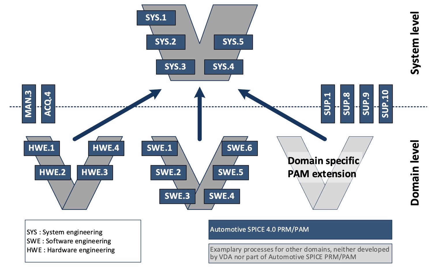
Figure C. 1 — The “Plug-in” concept
Annex C.2 “Element”, “Component”, and “Unit”
The following figure depicts the relationships between system elements, software components, and software units which are used consistently in the engineering processes. See the Terminology in Annex C to learn about the definitions of these terms.
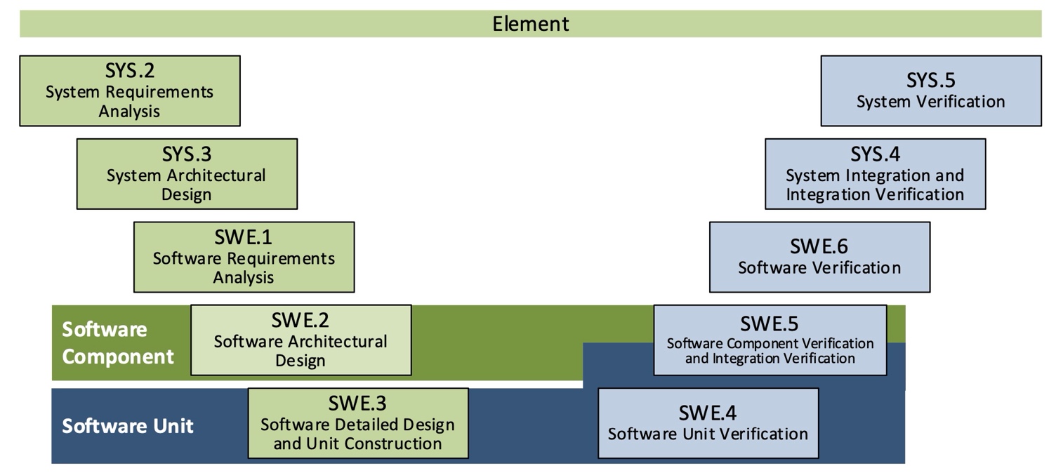
Figure C. 2 — Element, component, and unit
Annex C.3 Integration of Machine Learning Engineering Processes
The following figure shows how the Machine Learning Engineering Processes are integrated within the engineering V-Cycle perspective. Usually, the MLE “Machine Learning Engineering” processes are used in a highly iterative way.
Within the Software Architecture software elements shall be identified which need to be developed with machine learning. For these ML-based software elements the MLE processes apply, for other software components SWE.3 “Software Detailed Design & Unit Construction” and SWE.4 “Software Unit Verification” applies. After the successful testing of the ML-based software elements they need to be integrated with the other software components by applying SWE.5 “Software Integration & Integration Test”.
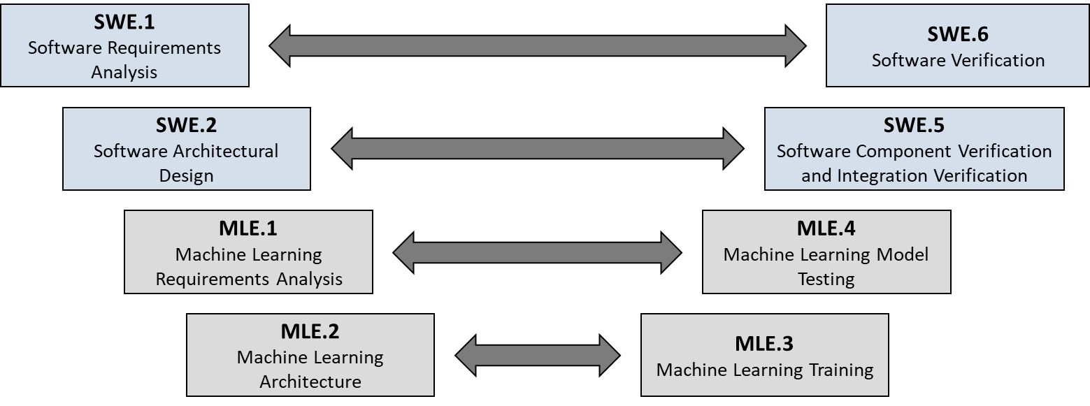
Figure C. 3 — Integration of MLE Processes
The second figure shows the interdependencies within the MLE “Machine Learning Engineering” process group and to the SUP.11 “Machine Learning Data Management”.
With MLE.1 “Machine Learning Requirements Analysis”, machine learning related Software requirements allocated to the ML-based software elements need to be refined into a set of ML requirements. These requirements must contain ML data requirements which are input for the SUP.11 “Machine Learning Data Management” and other ML requirements which are input for the other MLE “Machine Learning Engineering” processes.
By applying the SUP.11 “Machine Learning Data Management” process ML data with assured quality and integrity, which fulfill the ML data requirements, are collected, processed, and made available to all affected parties.
The other ML requirements should be used within the MLE.2 “Machine Learning Architecture” process to develop an ML architecture supporting training and deployment. Therefore, the ML architecture must contain all necessary ML architectural elements like hyperparameter ranges and initial values, details of the ML model, and possible other software parts which are necessary for MLE.3 “Machine Learning Training”. These other software parts should be developed according to SWE.3 “Software Detailed Design & Unit Construction” and SWE.4 “Software Unit Verification”.
Performing MLE.3 “Machine Learning Training” should start with specifying an ML training and validation approach. Based on this approach a training and validation dataset need to be created from the ML data pool provided by SUP.11 “Machine Learning Data Management” which is then used iteratively to optimize the ML model weights and hyperparameter values. When training exit criteria are reached the trained model should be agreed and communicated to all affected parties.
MLE.4 “Machine Learning Model Testing” focuses on testing the agreed trained model to ensure compliance with the ML requirements. Therefore, an ML test approach needs to be specified and an ML test dataset must be created from the provided ML data pool.
The ML test approach defines besides other details the distribution of data characteristics (e.g., sex, weather conditions, street conditions within the ODD) defined by ML requirements. The test dataset contains different test scenarios applying the required distribution of data characteristics e.g., driving during rain on a gravel road.
After successful testing the trained model, a deployed model is derived and tested as well. The deployed model will be integrated into the target system and may differ from the trained model which often requires powerful hardware and uses interpretative languages. Finally, the agreed test results and the deployed model must be communicated to all affected parties, so that the deployed model can be integrated with the other software units by applying SWE.5 “Software Integration and Integration Test”.
Figure C. 4 — Interdependencies within MLE and SUP.11
Annex C.4 Example of an ML Architecture
The following figure shows an example of an ML architecture, describing the overall structure of the ML-based software element and the interfaces within the ML-based software element and to other software elements. The ML architecture typically consists of an ML model and other ML architectural elements, which are other (classical) software components developed according to SWE.3 “Software Detailed Design & Unit Construction” and SWE.4 “Software Unit Verification” and provided to train, deploy and test the ML model. Furthermore, the ML architecture describes details of the ML model like used layers, activation functions, loss function, and backpropagation.
Figure C. 5 — Example of an ML Architecture
During training, hyperparameters (see appendix c #hyperparameters) defining the ML model will change therefore it is recommended to define ranges of hyperparameter values and initial values for training start are defined. Because developing an ML-based software element is highly iterative changes in the ML architecture might come up.
Furthermore, the ML architecture used for training can differ from the architecture of the deployed model, which will be integrated with the other software elements, these differences are part of the ML architecture as well.
Annex C.5 Traceability and consistency
Figure C. 6 (Figure C.2) — Consistency and traceability between system and software work products
Figure C. 7 (Figure C.3) — Consistency and traceability between system and hardware work products
Figure C. 8 (Figure C.4) — Consistency and traceability between ML work products
Annex C.6 “Agree” and “Summarize and Communicate”
The information flow on the left side of the “V” is ensured through a base practice “Communicate agreed ‘work product x’”. The term “agreed” here means that there is a joint understanding between affected parties of what is meant by the content of the work product.
The information flow on the right side of the “V” is ensured through a base practice “Summarize and communicate results”. The term “Summarize” refers to abstracted information resulting from test executions made available to all affected parties.
These communication-oriented base practices do not require a planning-based approach, nor a formal approval, confirmation, or release, as this is targeted at by GP 2.1.6 on capability level 2. At capability level 1 the communication-oriented base practices mean that the work products (or their content) are to be disseminated to affected parties.
An overview of these aspects is shown in the following figure:
Figure C. 9 — Agree, summarize and communicate
Annex C.7 Key Changes in Automotive SPICE 4.0
Terminology – “Measure” vs. “Metric”
In the English literature the term “measure” can mean both
“to find the size, quantity, etc. of something in standard units, ‘size/quantity’” and “… to judge the importance, value or effect of something”, respectively
“a plan of action or something done”
In PAM v3.1, both meanings were inconsistently used in e.g.:
MAN.5.BP6
MAN.6
PIM.3.BP7 Note 10
work product characteristics 07-00 “Measure“ and 07-xx
In the assessment practice, this sometimes led to misconceptions with interpreting these assessment indicators and, thus, to varying assessment results. Since it was one of the objectives for Automotive SPICE 4.0 to use terminology more homogeneously, the decision was to consistently use the following terms and meaning:
Quantitative measurement – “metric
“A plan of action” – “measure”
“To act in an operational manner” – “action”
Terminology – “Affected Party” (Level 1) vs. “Involved Party” (Level 2)
Processes at capability level 1 use the term “affected party” in the context of BP “Communicate”. This is to indicate that for every process instance A there is a downstream process instance B that requires the technical (i.e., capability level 1) output of A as a necessary input. Otherwise, process instance B would not be able to proceed, or update its output.
In contrast, “involved party” at capability level 2 includes, but goes beyond “affected parties”. For example, there may be a stakeholder who
is passively kept in the information loop (e.g., a line manager, steering committee);
is providing input (e.g., a deadline, a particular resource) and only requiring a commitment, but no further active involvement.
Affected parties thus are a subset of involved parties.
Terminology – “Verification” instead of “Testing”
The former Automotive SPICE V3.1 process SUP.2 Verification has been removed in favor of advancing the respective SWE and SYS processes from pure testing to verification. The motivation for this was:
SUP.2 was vague in regards to what ‘verification‘ should consider in contrast to testing processes
Especially at the system level, testing is not the only verification approach. Rather, measurements (e.g., geometrical tolerances), calculations or analyses (e.g., strength/stress calculation using an FEM method), or simulations instead of using physical samples are other types of verification. The same is true for mechanical or hardware development. Therefore, the umbrella term verification now forms he center of those processes‘ purposes.
The process SWE.4 ‘Unit Verification’ has already been an exception as a SW unit can be verified coherently by means of a combination of static analysis, testing, or code reviews (a view that is also inherent in ISO 26262-6 clause 9).
Annex D Reference standards
Annex D provides a list of reference standards and guidelines that support implementation of the Automotive SPICE PAM / PRM.
ISO/IEC 33001:2015 |
Information technology – Process assessment – Concepts and terminology |
|---|---|
ISO/IEC 33002:2015 |
Information technology – Process assessment – Requirements for performing process assessment |
ISO/IEC 33003:2015 |
Information technology – Process assessment – Requirements for process measurement frameworks |
ISO/IEC 33004:2019 |
Information technology – Process assessment – Requirements for process reference, process assessment and maturity models |
ISO/IEC 33020:2019 |
Information technology – Process assessment – Process measurement framework for assessment of process capability |
ISO/IEC/IEEE 24765:2017 |
Systems and software engineering – Vocabulary |
ISO/IEC/IEEE 29148:2018 |
Systems and software engineering – Life cycle processes – Requirements engineering |
INCOSE Guide for Writing Requirements |
|
PAS 1883:2020 |
Operational design domain (ODD) taxonomy for an automated driving system (ADS) |
ISO 26262:2018 |
Road vehicles — Functional safety, Second edition 2018-12 |